Document 13491556
advertisement
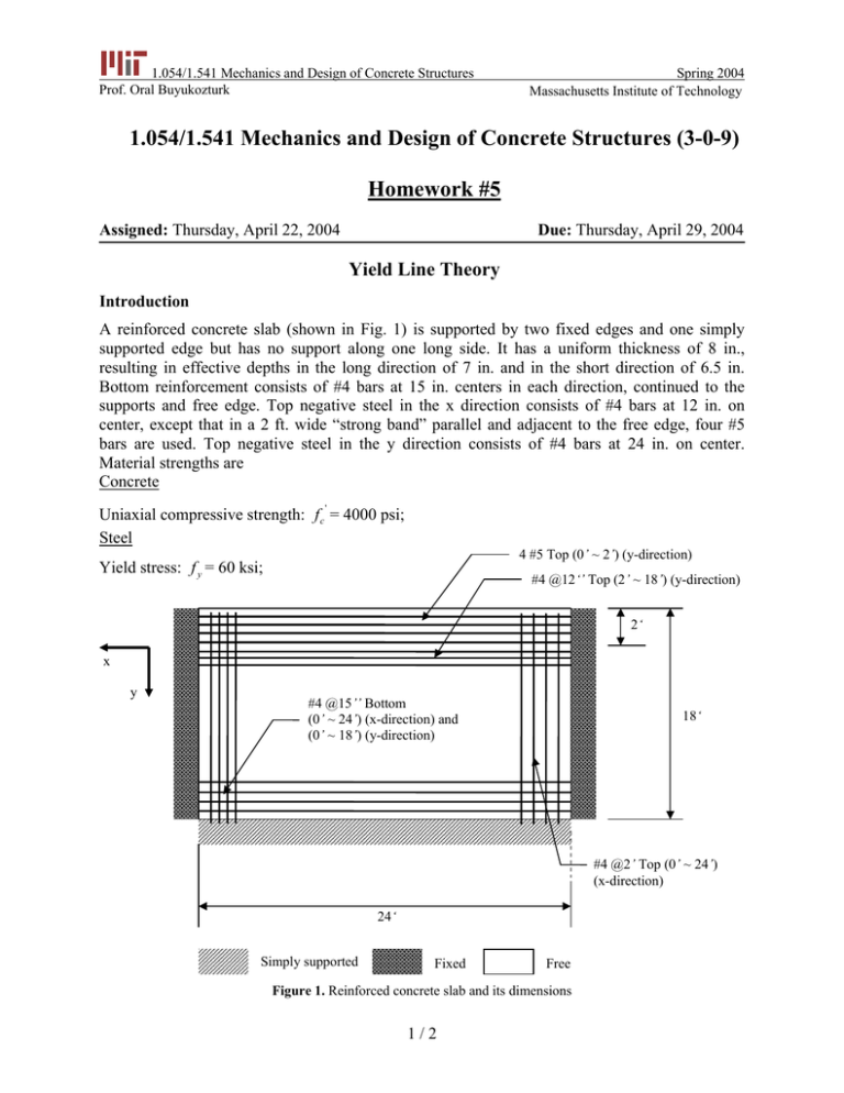
1.054/1.541 Mechanics and Design of Concrete Structures Prof. Oral Buyukozturk Spring 2004 Homework #5 Massachusetts Institute of Technology 1.054/1.541 Mechanics and Design of Concrete Structures (3-0-9) Homework #5 Assigned: Thursday, April 22, 2004 Due: Thursday, April 29, 2004 Yield Line Theory Introduction A reinforced concrete slab (shown in Fig. 1) is supported by two fixed edges and one simply supported edge but has no support along one long side. It has a uniform thickness of 8 in., resulting in effective depths in the long direction of 7 in. and in the short direction of 6.5 in. Bottom reinforcement consists of #4 bars at 15 in. centers in each direction, continued to the supports and free edge. Top negative steel in the x direction consists of #4 bars at 12 in. on center, except that in a 2 ft. wide “strong band” parallel and adjacent to the free edge, four #5 bars are used. Top negative steel in the y direction consists of #4 bars at 24 in. on center. Material strengths are Concrete ' Uniaxial compressive strength: f c = 4000 psi; Steel 4 #5 Top (0’ ~ 2’) (y-direction) Yield stress: f y = 60 ksi; #4 @12‘’ Top (2’ ~ 18’) (y-direction) 2‘ x y #4 @15’’ Bottom (0’ ~ 24’) (x-direction) and (0’ ~ 18’) (y-direction) 18‘ #4 @2’ Top (0’ ~ 24’) (x-direction) 24‘ Simply supported Fixed Free Figure 1. Reinforced concrete slab and its dimensions 1 / 2 1.054/1.541 Mechanics and Design of Concrete Structures Prof. Oral Buyukozturk Spring 2004 Homework #5 Question Using the yield line theory method, determine the ultimate load wu that can be carried by the slab. Note: z 7‘’ 6.5‘’ 8‘’ 6.5‘’ x 7‘’ y Figure 2. Illustration of the effeective depths in x- and y- directions 1. Fig. 2 is the partial illustration of the reinforced concrete slab in 3D, shown in Fig. 1. Notice that the given effective depths are valid for distances either from the top or the bottom. You will need these values to calculate positive and negative bending moments in the slab. 2. In y-direction, notice that the bending moment capacity of the cross section is NOT constant due to different spacings in two ranges (range 0’~2’ and range 2’~18’). You need to compute both of them for the virtual work, associated with their ranges, done by the slab (you CANNOT take average of them). 2 / 2
