Lab 3 – 7 Segment Display
advertisement

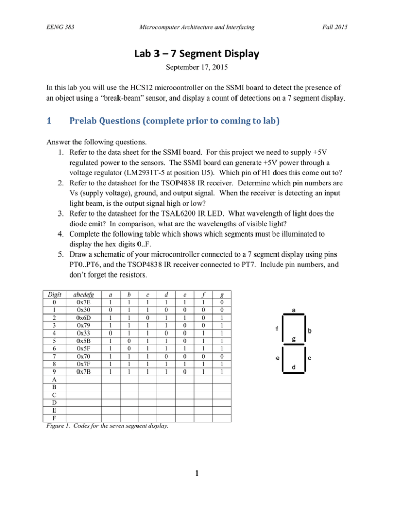
EENG 383 Microcomputer Architecture and Interfacing Fall 2015 Lab 3 – 7 Segment Display September 17, 2015 In this lab you will use the HCS12 microcontroller on the SSMI board to detect the presence of an object using a “break-beam” sensor, and display a count of detections on a 7 segment display. 1 PrelabQuestions(completepriortocomingtolab) Answer the following questions. 1. Refer to the data sheet for the SSMI board. For this project we need to supply +5V regulated power to the sensors. The SSMI board can generate +5V power through a voltage regulator (LM2931T-5 at position U5). Which pin of H1 does this come out to? 2. Refer to the datasheet for the TSOP4838 IR receiver. Determine which pin numbers are Vs (supply voltage), ground, and output signal. When the receiver is detecting an input light beam, is the output signal high or low? 3. Refer to the datasheet for the TSAL6200 IR LED. What wavelength of light does the diode emit? In comparison, what are the wavelengths of visible light? 4. Complete the following table which shows which segments must be illuminated to display the hex digits 0..F. 5. Draw a schematic of your microcontroller connected to a 7 segment display using pins PT0..PT6, and the TSOP4838 IR receiver connected to PT7. Include pin numbers, and don’t forget the resistors. Digit 0 1 2 3 4 5 6 7 8 9 A B C D E F Figure 1. abcdefg 0x7E 0x30 0x6D 0x79 0x33 0x5B 0x5F 0x70 0x7F 0x7B a 1 0 1 1 0 1 1 1 1 1 b 1 1 1 1 1 0 0 1 1 1 c 1 1 0 1 1 1 1 1 1 1 d 1 0 1 1 0 1 1 0 1 1 e 1 0 1 0 0 0 1 0 1 0 f 1 0 0 0 1 1 1 0 1 1 Codes for the seven segment display. 1 g 0 0 1 1 1 1 1 0 1 1 a f b g e c d EENG 383 2 Microcomputer Architecture and Interfacing Fall 2015 Regulated+5VPower For the remainder of the semester, it will be convenient to connect a wire from H1 to the protoboard on the SSMI board, to supply +5V regulated power to your circuits on the protoboard. The SSMI board has a voltage regulator that takes the +9V unregulated power from the adapter, and generates +5V regulated power. This signal is called “Vsharp” and comes out to header H1. Connect a wire from the pin corresponding to “Vsharp” on header H1, to the protoboard row labeled “+”. Verify with the multimeter that this is +5V. Just leave that wire in place for the remainder of the semester, so that the protoboard always has a +5V connection. (Note – the voltage regulator that produces Vsharp only produces up to 100 mA. This is enough to power logic circuitry, LEDs, etc, but it is not enough to power motors. ) 3 SevenSegmentDisplay Connect the seven segment display to Port T, using seven current limiting resistors (or just use the resistor DIP part provided in the kit). Sign-Off 1: Let the instructor check your connections. Then connect the power adapter to the board. Write a C program to have your display count up from 0 to F (and then reset to 0), with each digit displayed for one second. Have the program repeat forever. You may find it helpful to first manually write the various codes to Port T to make sure that the correct LEDs light up (recall how you did this in the previous lab). Sign-Off 2: Demonstrate the program to the instructor. 4 Break‐BeamSensor As discussed in lecture, a “break-beam” sensor can be constructed using an infrared (IR) light emitting diode and an IR receiver. When an object comes between the transmitter and receiver, it “breaks the beam” and this event can be detected and counted. To avoid unwanted sensitivity to ambient light, we will use a 38 kHz modulated signal for the transmitter. The receiver is designed to detect only IR light that is modulated by this frequency. The range of the receiver can be several meters or more, with a reasonably bright transmitter. We will generate a 38 kHz signal using the function generator. Connect the BNC adapter to the “TTL” output of the function generator. Check the frequency of the output signal with the oscilloscope and adjust the function generator to generate a 38 kHz signal. 2 EENG 383 Microcomputer Architecture and Interfacing Fall 2015 Get a little protoboard from the lab instructor and put the IR LED from your kit on the protoboard. Connect the output of the function generator to the IR LED in series with the 80 ohm resistor in your kit. Now put the TSOP4838 IR receiver on the protoboard on the SSMI board, and connect its power and ground pins. Power should be connected to +5V coming from “Vsharp”. With the transmitter light shining on the receiver, check the signal output of the IR receiver (with the oscilloscope or multimeter). Verify that the output signal changes when the beam is blocked. Now connect the output pin of the IR receiver to pin PT7 of the microcontroller. Modify your program so that instead of counting up every second, it only counts up when you get a new detection1 from the break beam sensor. The count of detections should be displayed on the 7 segment LED display. Of course, the 7 segment display can only display up to 15 decimal, so above 15 it will wrap around to zero (i.e., it displays the count modulo 16). Sign-Off 3: Demonstrate the program to the instructor. Include in your report: A description of the circuits used and the schematics A flowchart or pseudo code describing the algorithms The C language programs (with comments). Report the size of your program, in terms of the number of lines of source code, and the number of bytes of machine code. 1 The program should count each “break” only once, not multiple times. 3 EENG 383 Microcomputer Architecture and Interfacing Fall 2015 Lab 3: 7‐Segment Display Name: ________________________________Name: ________________________________ Task Description Sign-Off 1 Verify 7-Segment Display Implementation Sign-Off 2 7-Segment Display Counter Sign-Off 3 Demonstrate break beam sensor program to the instructor Initials 5 Rubric Deliverables 17 pts Pre-Lab Program with Flowchart/psuedocode /7 Schematic / 5 Demonstrations Circuit Explanation /5 Composition 5 pts Questions 5 pts /5 23 pts Sign-Off 1: 7-Segment Implementation /5 Sign-Off 2: 7-Segment Display Counter /10 Sign-Off 3: Break beam program Total / 50 pts 4 /8


