International Journal of Application or Innovation in Engineering & Management... Web Site: www.ijaiem.org Email: , Volume 2, Issue 12, December 2013
advertisement

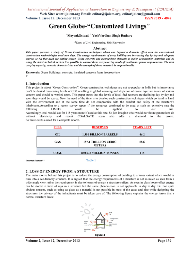
International Journal of Application or Innovation in Engineering & Management (IJAIEM) Web Site: www.ijaiem.org Email: editor@ijaiem.org, editorijaiem@gmail.com Volume 2, Issue 12, December 2013 ISSN 2319 - 4847 Green Globe-“Customized Livings” 1 MayankOstwal, 2 YashVardhan Singh Rathore 1,2 Dept. of Civil Engineering, SRM University Abstract This paper presents a study of Green Construction techniques which can impend a dramatic effect over the conventional construction methodologies used now days. The energy requirements of every building are increasing day by day and adequate sources to fill that need are getting scarce. Using concrete and isopropylene elements as major construction materials and by using the latest technical devices it is possible to control these overpowering needs of continuous power requirements. The heat carrying capacity, acoustic characteristics and the strength of these materials is unquestionable. Keywords: Green Buildings, concrete, insulated concrete foam, isopropylene. T 1. Introduction This project is about “Green Construction”. Green construction techniques are not so popular in India but its importance can’t be denied. Increasing levels of CO2 resulting in global warming and depletion of ozone layer are issues of serious concern and should be worked upon. This paper states that the levels of fossil fuel reserves are declining day by day and soon they would be scarce. Now the need of the time is to develop such construction techniques which go hand in hand with the environment and at the same time do not compromise with the comfort and safety of the structure’s inhabitants.According to a recent survey report if the resources continued to be used at such an extensive rate the following LIMITS would be applied to our use. Accordingly, coal would last for 118 years more if used at this rate. So just imagine what would our future generations do without electricity and recent COALGATE scam also adds a diamond to the crown. So there exists a need for a complete reform. FUEL RESERVES YEARS LEFT OIL 1,386 BILLION BARRELS 46.2 GAS 187.1 TRILLION CUBIC METERS 58.6 COAL 860,938 MILLION TONNES 118 Internet Sources** Table 1 2. LOSS OF ENERGY FROM A STRUCTURE The main motive behind this project is to reduce the energy consumption of building to a lower extent which would in turn into a eco-friendly structure. It is argued that the energy requirements of a structure is not so much as seen from a wide angle view rather the requirement is due to losses of energy a structure suffers. As seen in glass house effect energy can be stored in form of rays in a structure but the same phenomenon is not applicable in day to day life. For quite obvious reasons, such as using as glass as a material is not possible in most of the cases and also while designing the structures the privacy of the inhabitants must be taken care of. The following figure explains the energy losses that a normal structure faces: Figure 3 Volume 2, Issue 12, December 2013 Page 139 International Journal of Application or Innovation in Engineering & Management (IJAIEM) Web Site: www.ijaiem.org Email: editor@ijaiem.org, editorijaiem@gmail.com Volume 2, Issue 12, December 2013 ISSN 2319 - 4847 The above diagram is an approximation of the amount of energy lost from a structure and the contributing parts of the structure are shown. It is clear from the figure that around 70% of energy is lost from walls, roofs, basement and openings of the structure. Remaining 30% of energy loss is due to heat transmission. Therefore it is clearly stated that the requirements arise from these losses only. It is accepted that about 25%-35% of these losses are uncontrollable due to various reasons such as unavailability of proper control resources in every structure and the lack of sufficient fund to allow such practice. But it would be a very wise act if the remaining 65%-75% losses could be recovered. The need of the hour is to bring in the methods other than conventional methodologies which could cover these losses to a considerable level. 3. Defining the terms in ‘action’ R-Value: The R-value is a measure of thermal resistance of a structure. It is expressed as the thickness of the material divided by the thermal conductivity. For thermal resistance, we divide the unit thermal resistance by the area of the wall. Defining in scientific terms, under uniform conditions it is the ratio of the temperature difference across an insulator and the heat flux (heat transfer per unit area Q ) through it. Mathematically, R= Q Units of ‘R’ are given in Btu. There are many factors that come into play when using R-values to compute heat loss for a particular wall. One could double the R-value of insulation installed between framing members and realize substantially less than a 50% reduction in heat loss. The R value measures the material’s ability to decrease the rate of heat flow. The primary mode of heat transfer impeded by insulation is conduction, but insulation also reduces heat loss by all three heat transfer modes: conduction, convection, and radiation. Thermal mass: Thermal mass is a concept in building design that describes how the mass of the building provides "inertia" against temperature fluctuations, sometimes known as the thermal flywheel effect. For example, when outside temperatures are fluctuating throughout the day, a large thermal mass within the insulated portion of a house can serve to "flatten out" the daily temperature fluctuations .Thermal mass is a concept in building design that describes how the mass of the building provides "inertia" against temperature fluctuations, sometimes known as the thermal flywheel effect. For example, when outside temperatures are fluctuating throughout the day, a large thermal mass within the insulated portion of a house can serve to "flatten out" the daily temperature fluctuations. Thermal mass is effective in improving building comfort in any place that experiences these types of daily temperature fluctuations—both in winter as well as in summer. When used well and combined with passive solar design, thermal mass can play an important role in major reductions to energy use in active heating and cooling systems. The terms heavy-weight and light-weight are often used to describe buildings with different thermal mass strategies, and affects the choice of numerical factors used in subsequent calculations to describe their thermal response to heating and cooling. 4. Theme of the project The very idea of making a building sustainable is to make it ‘green’. Not in sense of colour but in the sense in which it responds to the environment. Various efforts till date are made in this direction but implementation takes time. Following the fundamental concerns to ‘Customize’ a conventionally constructed building into an eco-friendly structure: To recognize the importance of change in the concrete house and to make the average homeowner aware of the real benefits resulting in better future. To design a house using both conventional and alternate construction materials. To create homes and buildings that are more energy efficient, stronger, more sound resistant and more environmentally sustainable. To present the different opportunities and measures for reducing energy use in buildings without sacrificing comfort levels. The above listed are the focused areas of the project. The broad aim is to minimize the energy consumption of the building which could be achieved by following: 1. A building plan which places functions in locations that minimize the need for applied energy. 2. A shape which encourages the use of daylight and natural ventilation, and reduces heat losses. 3. An orientation that takes account of the potential benefits from solar gains while reducing the risk of glare and overheating. 4. Effective use of natural daylight combined with the avoidance of glare and unwanted solar gains. 5. Good levels of thermal insulation and prevention of unwanted air infiltration through the building envelope. Volume 2, Issue 12, December 2013 Page 140 International Journal of Application or Innovation in Engineering & Management (IJAIEM) Web Site: www.ijaiem.org Email: editor@ijaiem.org, editorijaiem@gmail.com Volume 2, Issue 12, December 2013 ISSN 2319 - 4847 5. The main ingredient of ‘Recipe’ All the features of a green building cannot be achieved by using architectural prospects alone. There must be a materialistic approach in the range. The thermal mass property and the R-Value supporting the energy loss control can be defended by using a very common yet very useful material known as ‘concrete’. A common perception of concrete is that it’s cold in winter and warm in summer. This perception is not correct since the concrete mass can be used for heat retention and ultimately energy saving. Energy efficiency comes from two factors: their thermal capacity is better than the conventional brick walls. Compared to a conventional R-Value of 19, a properly insulated concrete house could have a value of R=30, making it more efficient in terms of heating in winter or cooling in summer. The other form of energy cost saving may come from the use of geothermal or solar energy to increase efficiency further.In use of concrete for residential applications, emphasis has been placed on the concrete, but the progress is very slow in changing the perception of concrete that is not very friendly material due to its “cold appearance” and has more disadvantages. Concrete retains heat by its very nature during production. When it is mixed it is exothermic in nature and creates heat, particularly if it is poured in insulated forms and it remains longer with it due to its thermal mass. This in turn allows the concrete to be more energy efficient. The that the task performed by the thermal mass property of concrete may also be done by using cavity but the strength factor of concrete cannot be denied. The following figures illustrates the loss of the thermal mass action of concrete. Figure 4 It can be interpreted from the above diagram that the concrete acts as an Energy reservoir and traps the energy from both the sides. During summer seasons heat waves tend to move from a region of higher pressure to a region of lower pressure thus resulting in movement of heat into the structure and vice-versa in winters and both of them are undesirable for the inhabitants. To put an energy barrier or an energy reservoir in between is the best way to guide these heat waves into a desirable space. 6. Insulated concrete Forms (ICFs) Insulated concrete forms are isopropylene based materials which work as a form to pour concrete and they stay in their place for the life time of the structure. The left-in-place forms not only provide a continuous insulation and sound barrier, but also a backing for drywall on the inside, and stucco, lap sliding, or brick on the outside and provide significant insulating capability.The technology of ICF was first established a strong marketplace in the late 1960’s in Europe, where wood resources were at premium and there was a strong tradition of building durable, long lasting structures with the stone and concrete.Self-supporting concrete form of rigid, low intensity foamed plastic, adapted to be left in place to provide insulation for a wall formed by such forms which have been filled with concrete. Figure 3 Volume 2, Issue 12, December 2013 Page 141 International Journal of Application or Innovation in Engineering & Management (IJAIEM) Web Site: www.ijaiem.org Email: editor@ijaiem.org, editorijaiem@gmail.com Volume 2, Issue 12, December 2013 ISSN 2319 - 4847 The horizontal reinforcement provided inside the polystyrene form maintains its rigidity against wind pressure and earthquake loads and making it a complete reinforced structure. Besides acting act as form to the concrete it also provides acoustic as well as aesthetic measures to the structure. Following are some of the major benefits of ICF: • COMFORT- Houses built with ICF walls have a much more even temperature throughout the day and night. They have virtually no “cold spots” and draughts are sharply reduced. • SOLIDITY- The rigidity of concrete construction reduces the flexibility in floors and reduces shifting and vibrations from the force of the wind or the slamming of doors. Sometimes if the door slams all of the window frames will produce noises due to vibrations. This is all due to vibro-weakness of conventional walls. • QUIETNESS- the ICF wall is six times more effective against sound transmission compared to the ordinary frame wall. This reduces noise from outside and allows construction of houses near highways. • ENERGY EFFICIENCY- The superior insulation, air tightness, and mass of the exterior walls cut the amount of energy needed for heating and cooling by 30%-40%. This can save substantially in utility costs in typical homes in order of several thousands. • DESIGN FLEXIBILITY- ICF houses can be completed with almost any interior and exterior finishes and can take as easily as wood frame. In fact, some interesting effects such as curved walls and frequent corners can be less expensive to build into ICF home. Apart from the above listed points, technical illustrations shows that ICFs show about double the R-Value than the conventionally constructed structural elements and this can be seen as follows: CONVENTIONAL WALL Wall-Outside Air Film- 0.17 Siding- Wood Bevel 0.80 1/2 “ Plywood Sheathing 0.63 3½"Fibreglass Batt 11.00 ½ “ Drywall 0.45 Inside Air Film 0.68 Total R-Value 13.7 ICF CONSTRUCTED WALL Polystyrene 2”- 11.8 Wall- Outside Air Film 0.17 Cast in place concrete 8”- 0.64 Polystyrene 2”- 11.68 Inside air film 0.68 Total R-Value 25.2 Table 2 Thus from the above table it is very clear that Insulated Concrete forms would prove twice as much as better than the conventional walls. 7. Structural elements. ICF construction is less demanding to build with owing to its modular design. Less skilled labour can be employed to lay the ICF forms though careful consideration must be made when pouring the concrete to make sure it consolidates fully and cures evenly without cracking. • Floors and Foundations: ICF decking is becoming an increasingly popular addition to general ICF wall construction. ICF decking weighs up to 40% less than standard concrete flooring and provides superior insulation. ICF decking can also be designed in conjunction with ICF walls to form a continuous monolithic structure joined together by rebar. ICF deck roofs are less common as it is difficult to pour concrete on an angled surface. • Walls: ICF walls are constructed one row at a time, usually starting at the corners and working outward. End blocks are then cut to fit so as to waste the least material possible. As the wall rises blocks are staggered to avoid long vertical seams which can weaken the formwork. Structure frames known as bucks are placed around openings to give added strength to the openings and serve as attachment points for windows and doors. 8. Advantages Related to Durability, Fire Resistance and Termite Concrete is strong and durable,when used properly. In addition to durability, concrete resists fire and wind and is not prone to termite attack. Experience has shown that concrete structures survive fire much more readily than structures built with other materials.Unlike wood, concrete does not burn; unlike steel, it does not soften and bend. Concrete does not break down until it is exposed to very high temperatures - far above the level in a typical house.When subjected to continuous gas flames and temperatures of up to 2000°F for 4 hour s, the ICF walls do not fail structurally having no significant breaks in the concrete layer. Concrete walls have also proven more resistant to allowing fire to pass from one Volume 2, Issue 12, December 2013 Page 142 International Journal of Application or Innovation in Engineering & Management (IJAIEM) Web Site: www.ijaiem.org Email: editor@ijaiem.org, editorijaiem@gmail.com Volume 2, Issue 12, December 2013 ISSN 2319 - 4847 side of the wall to the other, significant in areas where brush fires are more prevalent.High winds, hurricanes and tornadoes present the greatest hazard to homes. They create debris and flying objects, which can penetrate and destroy homes. The residential concrete walls have a much greater impact resistance to these hazards compared to the conventionally framed walls. Termite problem A concrete structure will provide a better protection against such natural problems. Except for utility openings, insects find it more difficult to enter the concrete house with both walls and floor of concrete. Termites have virtually no venue. In addition, the house will provide better dust protection . 9. Other Green Measures The above listed measures would definitely reduce the power consumption of the structure but there are also few technological devices which when conglomerated with this kind of structure would be a boon to it. They can be listed as follows: Lighting controls should be designed so that small groups of lights can be controlled individually with the controls provided adjacent to the work area. Perimeter lighting should be controlled separately to core lighting so that perimeter lights can be switched off when there is adequate daylight. Absence detection should be provided to rooms that are used intermittently. This should switch lights off automatically after a room or space has been unoccupied for a set period of time. Daylight sensors and timed switches should be used to preventexternal lighting being left on unnecessarily. Daylight sensors can also be used to switch off internal lighting when daylight levels are sufficient. References [1] “Green building incorporates high –tech engineering.” Motion System Design 50.7 (July 2008): 32(2). General OneFile. Gale. Goochland High School. 6 Oct. 2008 [2] Roodman, David M. (1995).A building revolution: How ecology and health concerns are transforming construction. Worldwatch Institute. [3] Daisey, J.M., Angell, W.J., and Apte, M.G. (2003). Indoor air quality, ventilation, and health symptoms in schools: An analysis of existing information. Indoor Air 13:53-64. [4] Research article by Prof. Dr.-Ing. Nicole Riedigerhttp://iti.vgtu.lt/sure/Media/Default/Presentations/Vilnius%202013%20HTW%20Berlin_Riediger.pdf [5] G.M. Sabnis, Sharda G. Sabnis, Edward J. Martin“ The energy efficient house” (Volume 1, Second Edition), 2011 Volume 2, Issue 12, December 2013 Page 143


