Document 12822788
advertisement
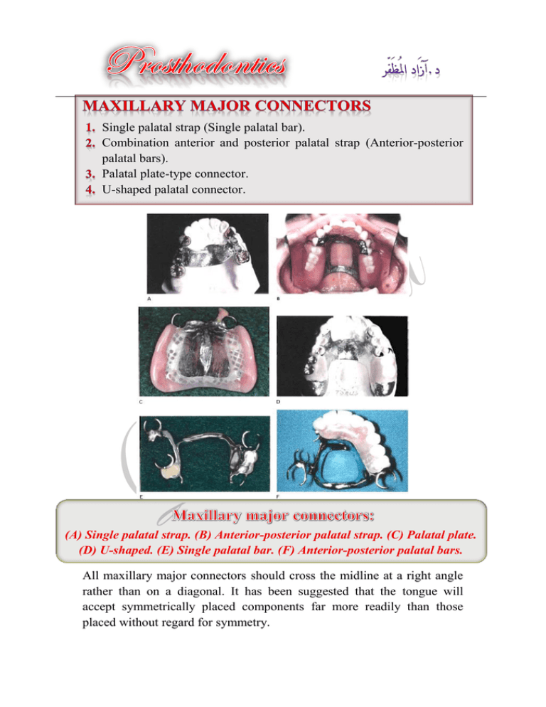
Single palatal strap (Single palatal bar). Combination anterior and posterior palatal strap (Anterior-posterior palatal bars). Palatal plate-type connector. U-shaped palatal connector. (A) Single palatal strap. (B) Anterior-posterior palatal strap. (C) Palatal plate. (D) U-shaped. (E) Single palatal bar. (F) Anterior-posterior palatal bars. All maxillary major connectors should cross the midline at a right angle rather than on a diagonal. It has been suggested that the tongue will accept symmetrically placed components far more readily than those placed without regard for symmetry. Indications 1- Posterior bilateral edentulous spaces of short span in a tooth-supported restoration. 2- It may also be used in tooth-supported unilateral edentulous situations with provision for cross-arch attachment by extracoronal retainers. Contraindications 1- Tooth-tissue supported removable partial denture. 2- Presence of palatal tori. 3- Extremely long edentulous span. Anteroposterior major connector would be better. Very simple design. Very few metal-tissue edges. It covers a considerable portion of the palate. Anatomic replica form. Anterior border follows the valleys between rugae as nearly as possible at right angles to median suture line. Posterior border is well anterior to the vibrating line, at right angle to median suture line. Strap should be 8 mm wide or approximately as wide as the combined width of a maxillary premolar and first molar. Confined within an area bounded by the four principal rests. In sagittal section, midportion of major connector demonstrates slight elevation to provide rigidity. Such thickness of major connector does not appreciably alter palatal contours. B To differentiate between a palatal bar and a palatal strap, a palatal connector component of less than 8 mm in width is called palatal bar. It is a rigid palatal major connector. The anterior and posterior palatal strap combination may be used in almost any maxillary partial denture design. The strength of this major connector design lies in the fact that the anterior and posterior components are joined together by longitudinal connectors on either side, forming a square or rectangular frame. Indications In Class I and II arches in which excellent abutment and residual ridge support exists, and direct retention can be made adequate without the need for indirect retention from palate (palatal plate). Long edentulous spans in Class II mod. 1 arches. In Class IV arches in which anterior teeth must be replaced with a removable partial denture. Inoperable palatal tori that do not extend posteriorly to the junction of the hard and soft palates. Contraindications 1- When can use simple major connector. 2- When there is large inoperable palatal torus that extends posteriorly to the soft palate, so broad U- shaped major connector may be considered. The double-strap type of major connector provides the maximum rigidity without bulk. It covers minimum of palatal tissues than full palatal coverage. Very complex design. A lot of metal-tissue edges. The posterior palatal bar or strap frequently does not fit the palate closely. The anterior border is frequently located in the rugae. Parallelogram shaped and open in center portion. Relatively broad (8 to 10 mm) anterior and posterior palatal straps. Lateral palatal straps (7 to 9 mm) narrow and parallel to curve of arch; minimum of 6 mm from gingival crevices of remaining teeth. Anterior palatal strap: anterior border not placed farther anteriorly than anterior rests and never closer than 6 mm to lingual gingival crevices; follows the valleys of the rugae at right angles to the median palatal suture. Posterior border, if in rugae area, follows valleys of rugae at right angles to the median palatal raphe. Posterior palatal connector: posterior border located at junction of hard and soft palates and at right angles to median palatal raphe and extended to hamular notch area(s) on distal extension side(s). Anatomic replica or matte surface. Anterio-posterior palatal strap Anterio-posterior palatal bar The words palatal plate are used to designate any thin, broad, contoured palatal coverage used as a maxillary major connector and covering one half or more of the hard palate. Indications of complete palatal coverage In Class II arch with large posterior modification space and some missing anterior teeth. When relining is anticipated or cost is a factor. In the absence of a pedunculated torus. In most situations in which only some or all anterior teeth remain. When the last remaining abutment tooth on either side of a Class I arch is the canine or first premolar tooth, especially when the residual ridges have undergone excessive vertical resorption. This may be accomplished in one of two ways. A- One method is to use a complete cast plate that extends to the junction of the hard and soft palates. B- The other method is to use a cast major connector anteriorly with retentive means posteriorly, for the attachment of an acrylic-resin denture base that extends posteriorly to the posterior palatal seal area. Contraindications When less than complete palatal coverage is necessary and there are sufficient remaining natural teeth to use a palatal plate or strap major connector. Maximum support, retention, bracing, and direct-indirect retention from the palate. Fairly simple design. Few metal teeth edges. Easy to add new prosthetic teeth to framework. Can be easily converted to an interim complete denture. Covers more teeth and tissues surface than any major connector. There are several design difficulties: A- The hamular notch, vibrating line area must be located on a master cast. B- Difficult to adjust the metal-tissue contact. C- Difficult to reline the metal portion of palatal contact. Anatomic replica form for full palatal metal casting supported anteriorly by positive rest seats. Palatal linguoplate supported anteriorly and designed for the attachment of acrylic resin extension posteriorly. Contacts all of the teeth remaining in the arch. Posterior border: terminates at the junction of the hard and soft palates; extended to hamular notch area(s) on distal extension side(s); at a right angle to median suture line. The U-shaped palatal major connector is the least favorable design of all palatal major connectors. Indications A class IV partially edentulous arch. A class III or class III mod.1 partially edentulous arch with anterior edentulous spaces, where cross-arch force distribution is not important. A partially edentulous arch with an inoperable palatal torus extends to the posterior limit of the hard palate. When several anterior teeth are to be replaced. Contraindications 1- Where support, retention, bracing, and direct-indirect retention from the palate is necessary. 2- Where cross-arch force distribution is necessary. Minimal coverage of the palate. Fairly simple design. Fewer metal-tooth or -tissue edges than anteroposterior design. It is not rigid as other maxillary major connectors; rigidity may be increased by having the metal in the vertical and horizontal planes. Its lack of rigidity (compared with other designs) can allow lateral flexure under occlusal forces, which may induce torque or direct lateral force to abutment teeth. It covers the rugae, which are highly enervated, this make the patient uncomfortable. Impinging the gingival tissue, this leads to gingival irritation and periodontal damage. For gaining good support for U-shaped major connector, the occlusal rests should be increase (unconservative). Where it must be used, indirect retainers must support any portion of the connector extending anteriorly from the principal occlusal rests. Anterior border areas of this type of connector must be kept at least 6 mm away from adjacent teeth. If for any reason the anterior border must contact the remaining teeth, the connector must again be supported by rests placed in properly prepared rest seats. It should never be supported even temporarily by inclined lingual surfaces of anterior teeth. Step 1: Outline of primary bearing areas. The primary bearing areas are those that will be covered by the denture base(s). Step 2: Outline of nonbearing areas. The nonbearing areas are the lingual gingival tissue within 5-6 mm of the remaining teeth, hard areas of the medial palatal raphe (including tori), and palatal tissue posterior to the vibrating line. Step 3: Outline of connector areas. Steps 1 and 2, when completed, provide an outline or designate areas that are available to place components of major connectors. Step 4: Selection of connector type. Selection of the type of connector is based on four factors: Mouth comfort. Rigidity. Location of denture bases. Need for indirect retention from palate. Connectors should be of minimum bulk and should be positioned so that interference with the tongue during speech and mastication is not encountered. Connectors must have a maximum of rigidity to distribute stress bilaterally. Step 5: Unification. After selection of the type of major connector, the denture base areas and connectors are joined. It is the scribing of a shallow groove (not in excess of 0.5 mm in width or depth) on the maxillary master cast outlining the palatal major connector exclusive of rugae areas. The purposes of beading are as follows: 1- To transfer the major connector design to the investment cast. 2- To provide a visible finishing line for the casting. 3- To ensure intimate tissue contact of the major connector with selected palatal tissue. 4- Preventing food from easily dislodging the prosthesis.
