5-31
advertisement
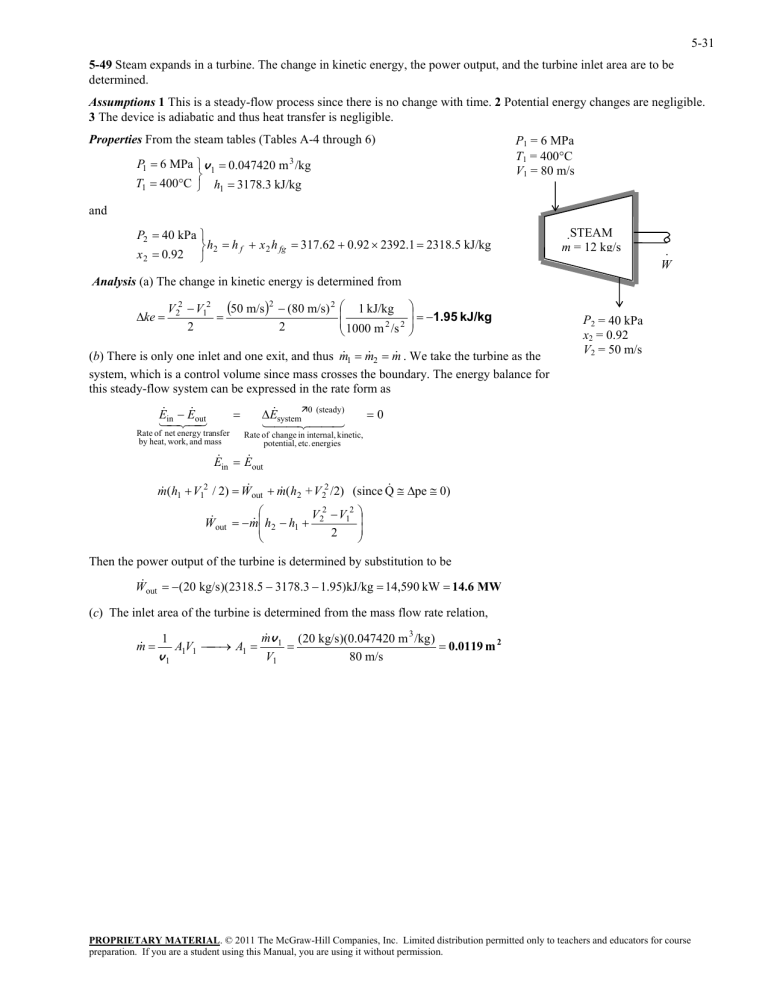
5-31 5-49 Steam expands in a turbine. The change in kinetic energy, the power output, and the turbine inlet area are to be determined. Assumptions 1 This is a steady-flow process since there is no change with time. 2 Potential energy changes are negligible. 3 The device is adiabatic and thus heat transfer is negligible. Properties From the steam tables (Tables A-4 through 6) P1 = 6 MPa T1 = 400C V1 = 80 m/s P1 6 MPa v 1 0.047420 m 3 /kg T1 400C h1 3178.3 kJ/kg and P2 40 kPa h2 h f x 2 h fg 317.62 0.92 2392.1 2318.5 kJ/kg x 2 0.92 · STEAM m = 12 kg/s · W Analysis (a) The change in kinetic energy is determined from ke V22 V12 50 m/s 2 (80 m/s) 2 2 2 1 kJ/kg 1000 m 2 /s 2 1.95 kJ/kg 1 m 2 m . We take the turbine as the (b) There is only one inlet and one exit, and thus m system, which is a control volume since mass crosses the boundary. The energy balance for this steady-flow system can be expressed in the rate form as E E out in Rate of net energy transfer by heat, work, and mass E system0 (steady) P2 = 40 kPa x2 = 0.92 V2 = 50 m/s 0 Rate of change in internal, kinetic, potential, etc. energies E in E out pe 0) m (h1 V12 / 2) W out m (h2 + V 22 /2) (since Q V 2 V12 W out m h2 h1 2 2 Then the power output of the turbine is determined by substitution to be W out (20 kg/s)(2318.5 3178.3 1.95)kJ/kg 14,590 kW 14.6 MW (c) The inlet area of the turbine is determined from the mass flow rate relation, m 1 v1 A1V1 A1 m v 1 (20 kg/s)(0.047420 m 3 /kg ) 0.0119 m 2 V1 80 m/s PROPRIETARY MATERIAL. © 2011 The McGraw-Hill Companies, Inc. Limited distribution permitted only to teachers and educators for course preparation. If you are a student using this Manual, you are using it without permission.
