W H UN N
advertisement
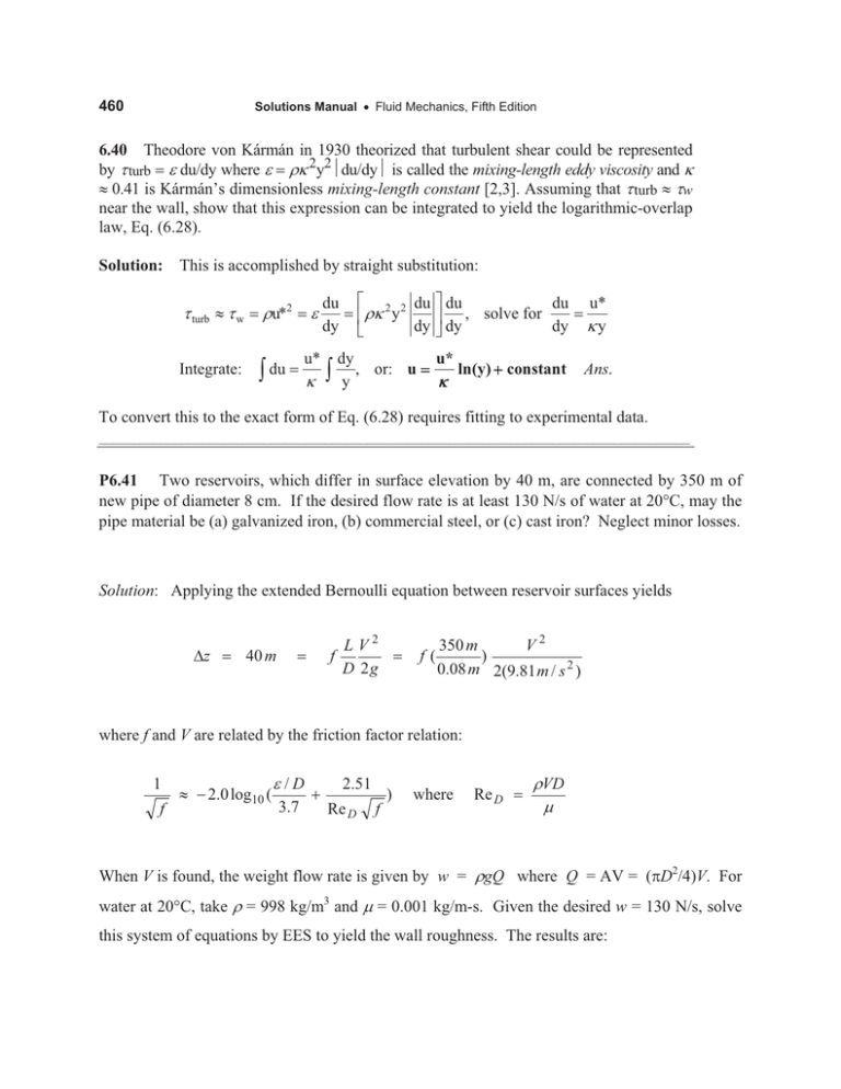
460 Solutions Manual x Fluid Mechanics, Fifth Edition 6.40 Theodore von Kármán in 1930 theorized that turbulent shear could be represented by W turb H dudy where H UN 2y2~du/dy~ is called the mixing-length eddy viscosity and N | 0.41 is Kármán’s dimensionless mixing-length constant [2,3]. Assuming that W turb | Ww near the wall, show that this expression can be integrated to yield the logarithmic-overlap law, Eq. (6.28). Solution: This is accomplished by straight substitution: W turb | W w Integrate: H du dy u* ³ Uu*2 ³ du N ª 2 2 du º du du « UN y » , solve for dy ¼ dy dy ¬ dy , or: u y u* N ln(y) constant u* Ny Ans. To convert this to the exact form of Eq. (6.28) requires fitting to experimental data. ______________________________________________________________________________________ P6.41 Two reservoirs, which differ in surface elevation by 40 m, are connected by 350 m of new pipe of diameter 8 cm. If the desired flow rate is at least 130 N/s of water at 20qC, may the pipe material be (a) galvanized iron, (b) commercial steel, or (c) cast iron? Neglect minor losses. Solution: Applying the extended Bernoulli equation between reservoir surfaces yields 'z 40 m f L V2 D 2g f( 350 m V2 ) 0.08 m 2(9.81 m / s 2 ) where f and V are related by the friction factor relation: 1 f | 2.0 log10 ( H /D 3.7 2.51 Re D f ) where Re D UVD P When V is found, the weight flow rate is given by w = UgQ where Q = AV = (SD2/4)V. For water at 20qC, take U = 998 kg/m3 and P = 0.001 kg/m-s. Given the desired w = 130 N/s, solve this system of equations by EES to yield the wall roughness. The results are: 461 Chapter 6 x Viscous Flow in Ducts f = 0.0257 ; V = 2.64 m/s ; ReD = 211,000 ; Hmax = 0.000203 m = 0.203 mm Any less roughness is OK. From Table 6-1, the three pipe materials have (a) galvanized: H = 0.15 mm ; (b) commercial steel: H = 0.046 mm ; cast iron: H = 0.26 mm Galvanized and steel are fine, but cast iron is too rough.. Ans. Actual flow rates are (a) galvanized: 135 N/s; (b) steel: 152 N/s; (c) cast iron: 126 N/s (not enough) 6.42 It is clear by comparing Figs. 6.12b and 6.13 that the effects of sand roughness and commercial (manufactured) roughness are not quite the same. Take the special case of commercial roughness ratio H /d 0.001 in Fig. 6.13, and replot in the form of the wall-law shift 'B (Fig. 6.12a) versus the logarithm of H H u/Q. Compare your plot with Eq. (6.45). Solution: To make this plot we must relate 'B to the Moody-chart friction factor. We use Eq. (6.33) of the text, which is valid for any B, in this case, B Bo 'B, where Bo | 5.0: V 1 § Ru* · 3 V | ln ¨ Bo 'B , where ¸ u* N © Q ¹ 2N u* 8 f and Ru* Q 1 f Re d 2 8 (1) Combine Eq. (1) with the Colebrook friction formula (6.48) and the definition of H: 1 § H /d 2.51 · (2) | 2.0 log10 ¨ © 3.7 Re f ¹̧ f H u* H H f and H Re d (3) Q 8 d d Equations (1, 2, 3) enable us to make the plot below of “commercial” log-shift 'B, which is similar to the ‘sand-grain’ shift predicted by Eq. (6.45): 'Bsand | (1/N)ln(H) 3.5. B Ans. Fig. P6.42 ______________________________________________________________________________________
