Darcy Wiesbach Equation
advertisement
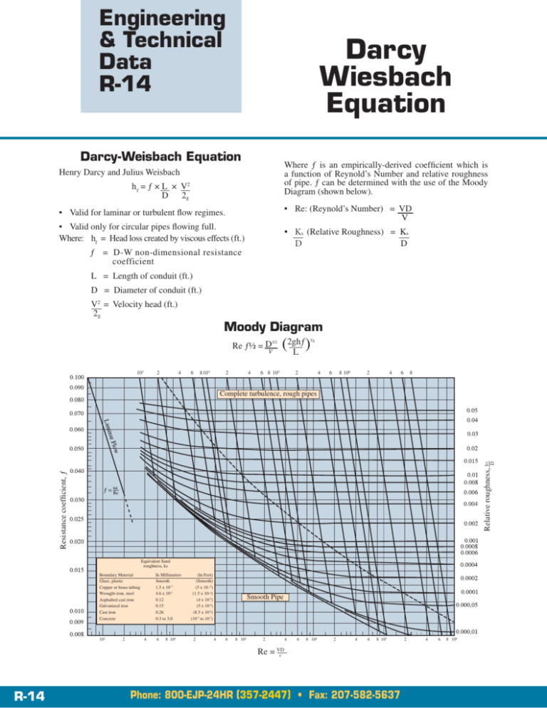
Engineering & Technical Data R-14 Darcy Wiesbach Equation Darcy-Weisbach Equation Where ƒ is an empirically-derived coefficient which is a function of Reynold’s Number and relative roughness of pipe. ƒ can be determined with the use of the Moody Diagram (shown below). Henry Darcy and Julius Weisbach h f = ƒ × L × V2 D 2g • Re: (Reynold’s Number) = VD V • Valid for laminar or turbulent flow regimes. • Valid only for circular pipes flowing full. Where: hf = Head loss created by viscous effects (ft.) ƒ = D-W non-dimensional resistance coefficient L = Length of conduit (ft.) D = Diameter of conduit (ft.) V2 = Velocity head (ft.) 2g • K s (Relative Roughness) = Ks D D Moody Diagram Re ƒ½ = D v 3/2 103 2 4 6 810 4 2 4 (2ghƒ ) L ½ 6 8 10 5 2 4 6 8106 2 4 6 8 Resistance coefficient, ƒ Relative roughness, ks D Complete turbulence, rough pipes Boundary Material Glass, plastic Copper or brass tubing Wrought iron, steel Asphalted cast iron Galvanized iron Cast iron Concrete 103 2 In Millimeters Smooth 1.5 x 10⁻³ 4.6 x 10⁻² 0.12 0.15 0.26 0.3 to 3.0 4 6 8 104 Equivalent Sand roughness, ks (In Feet) (Smooth) (5 x 10 -6) (1.5 x 10⁻⁴) (4 x 10⁻⁴) (5 x 10⁻⁴) (8.5 x 10⁻⁴) (10-3 to 10-2) 2 Smooth Pipe 4 6 8 105 2 R-14 4 6 8 106 2 4 6 8 107 Re = VD v Phone: 800-EJP-24HR (357-2447) • Fax: 207-582-5637 2 4 6 8 108
