16.901: Finite Element Method Project Heat Transfer in a Turbine Blade 1
advertisement

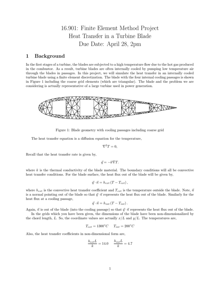
16.901: Finite Element Method Project Heat Transfer in a Turbine Blade Due Date: April 28, 2pm 1 Background In the first stages of a turbine, the blades are subjected to a high temperature flow due to the hot gas produced in the combustor. As a result, turbine blades are often internally cooled by pumping low temperature air through the blades in passages. In this project, we will simulate the heat transfer in an internally cooled turbine blade using a finite element discretization. The blade with the four internal cooling passages is shown in Figure 1 including the coarse grid elements (which are triangular). The blade and the problem we are considering is actually representative of a large turbine used in power generation. Figure 1: Blade geometry with cooling passages including coarse grid The heat transfer equation is a diffusion equation for the temperature, ∇2 T = 0, Recall that the heat transfer rate is given by, ~q = −k∇T. where k is the thermal conductivity of the blade material. The boundary conditions will all be convective heat transfer conditions. For the blade surface, the heat flux out of the blade will be given by, q~ · ~n = hext (T − Text ) , −0.2 where hext is the convective heat transfer coefficient and T ext is the temperature outside the blade. Note, ~n is a normal pointing out of the blade so that q~ · ~n represents the heat flux out of the blade. Similarly for the heat flux at a cooling passage, q~ · ~n = hint (T − Tint ) . 0 0.2 0.4 0.6 0.8 1 Again, ~n is out of the blade (into the cooling passage) so that q~ · ~n represents the heat flux out of the blade. In the grids which you have been given, the dimensions of the blade have been non-dimensionalized by the chord length, L. So, the coordinate values are actually x/L and y/L. The temperatures are, Text = 1300◦C Tint = 200◦ C Also, the heat transfer coefficients in non-dimensional form are, hint L = 4.7 k hext L = 14.0 k 1 Grid Coarse Medium Fine Nodes hmax Tmax Tmin CPU Time Table 1: Comparison of number of nodes, cell size, minimum and maximum blade temperatures, and CPU time for three grids. 2 Tasks 2.1 Finite Element Method Implementation The first task is to develop an FEM solver for this problem. Three grids of triangular elements have been gen® erated for the blade. The data are stored in the MATLAB datafiles g0012coarse.mat, g0012medium.mat, and g0012fine.mat (Note: since these datafiles are stored in a binary form, you cannot edit it). A skeleton ® MATLAB source code for your solver is in bladeheat.m. Please read the comments in the source code both for information on how the grid data is stored and for how to write the rest of the code. Documentation for this task is as follows: ® • A thoroughly commented MATLAB source code (or codes if you broke the solver into more than module). You will be graded on the clarity by which your comments describe what you are doing in the code. Your comments should be descriptive enough for a person with some exposure to heat transfer and Finite Element Methods to clearly understand everything you are doing in the code. • Plots of the temperature distributions on all three grids. • Note: since the algorithm is a standard FEM discretization of Laplace’s equation, no other description of the algorithm is required beyond that provided in the source code. 2.2 Study of Accuracy and Work Though we do not have an exact solution to this problem, we can study how the results from the simulations change with increasing mesh size. Specifically, for all grids, fill in Table 1. To calculate the grid size h max , use the following approach: • For each element, calculate the radius of the circle which can be drawn through the three nodes of the triangular element. • Set hmax to the maximum value of all element radii. Discuss the trends you observe in h max , Tmax , Tmin , and CPU time versus the number of nodes in the grids. If the accuracy of the temperature throughout the blade needed to be within 10 ◦ C of the exact answer, what grid (if any) would you recommend using based on this study. 2.3 Design Recommendations Based on the results of the simulation, what approach(es) would you recommend for improving the internal cooling design to lower the temperatures in the blades? ® MATLAB is a trademark of The MathWorks, Inc. 2


