AN-625
APPLICATION NOTE
One Technology Way • P.O. Box 9106 • Norwood, MA 02062-9106 • Tel
T : 781/329-4700 • Fax: 781/326-8703 • www.analog.com
Modifying the Range of the ADXRS150 and ADXRS300 Rate Gyros
by Harvey Weinberg
INTRODUCTION
The ADXRS150 and ADXRS300 rate gyros have a
dynamic range of 150°/s and 300°/s, respectively. In
some cases a user may wish to have a dynamic range or
scale factor other than what is offered. This application
note will discuss three techniques that can be used to
modify the dynamic range to provide about one third the rated dynamic range to several thousand degrees per second.
INCREASING THE SCALE FACTOR
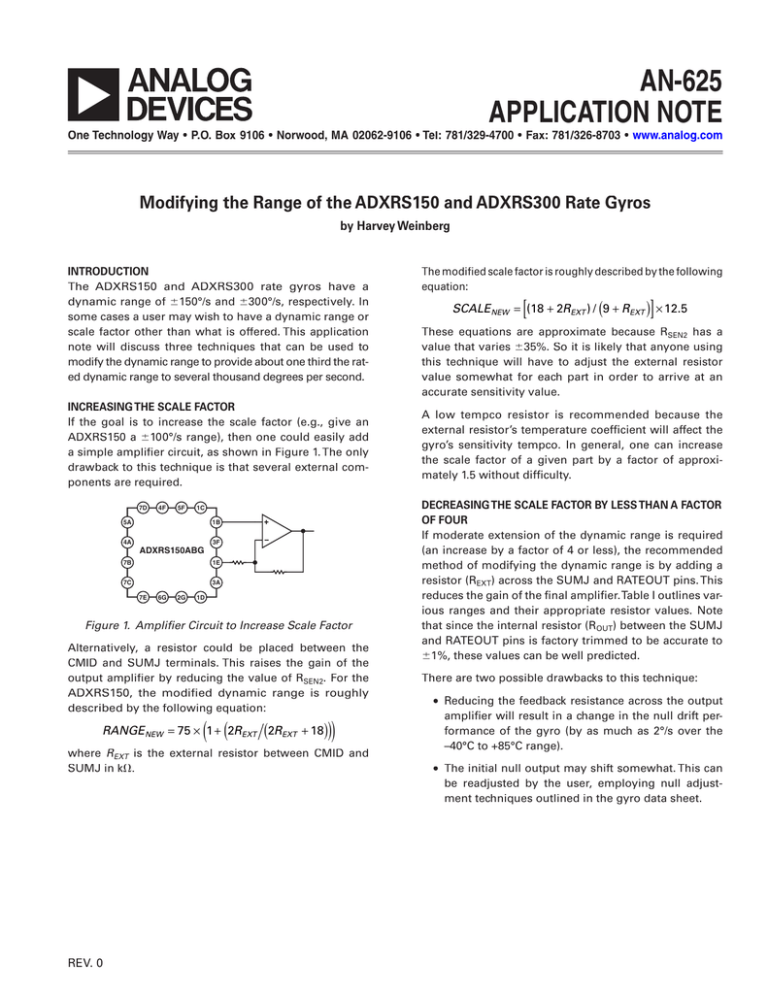
If the goal is to increase the scale factor (e.g., give an
ADXRS150 a 100°/s range), then one could easily add
a simple amplifier circuit, as shown in Figure 1. The only
drawback to this technique is that several external components are required.
7D
4F
5F
1C
5A
4A
1B
ADXRS150ABG
3F
1E
7B
7C
3A
7E
6G
2G
1D
Figure 1. Amplifier Circuit to Increase Scale Factor
Alternatively, a resistor could be placed between the
CMID and SUMJ terminals. This raises the gain of the
output amplifier by reducing the value of RSEN2. For the
ADXRS150, the modified dynamic range is roughly
described by the following equation:
( (
))
RANGE NEW = 75 ¥ 1 + 2REXT (2REXT + 18)
where REXT is the external resistor between CMID and
SUMJ in k.
The modified scale factor is roughly described by the following
equation:
[
]
SCALE NEW = (18 + 2REXT ) / (9 + REXT ) ¥ 12.5
These equations are approximate because RSEN2 has a
value that varies 35%. So it is likely that anyone using
this technique will have to adjust the external resistor
value somewhat for each part in order to arrive at an
accurate sensitivity value.
A low tempco resistor is recommended because the
external resistor’s temperature coefficient will affect the
gyro’s sensitivity tempco. In general, one can increase
the scale factor of a given part by a factor of approximately 1.5 without difficulty.
DECREASING THE SCALE FACTOR BY LESS THAN A FACTOR
OF FOUR
If moderate extension of the dynamic range is required
(an increase by a factor of 4 or less), the recommended
method of modifying the dynamic range is by adding a
resistor (REXT) across the SUMJ and RATEOUT pins. This
reduces the gain of the final amplifier. Table I outlines various ranges and their appropriate resistor values. Note
that since the internal resistor (ROUT) between the SUMJ
and RATEOUT pins is factory trimmed to be accurate to
1%, these values can be well predicted.
There are two possible drawbacks to this technique:
∑ Reducing the feedback resistance across the output
amplifier will result in a change in the null drift performance of the gyro (by as much as 2°/s over the
–40°C to +85°C range).
∑ The initial null output may shift somewhat. This can
be readjusted by the user, employing null adjustment techniques outlined in the gyro data sheet.
REV. 0
AN-625
ADXRS150
ADXRS300
REXT
(k)
Range
(°/s)
Scale
(mV/°/s)
Range
(°/s)
Scale
(mV/°/s)
536
267
178
133
107
88.7
76.8
66.5
60.4
200
250
300
350
400
450
500
550
600
9.4
7.5
6.2
5.3
4.7
4.1
3.7
3.4
3.1
400
500
600
700
800
900
1000
1100
1200
3.7
3.0
2.5
2.1
1.9
1.7
1.5
1.4
1.3
If one requires a dynamic range greater than ~5000°/s, a
combination of techniques may be used, such as adding
an external resistor and reducing the voltage at CP5. Using
an ADXRS300 with an external resistor of ~60 k and
a VCP5 of 5 V, a dynamic range of roughly 50,000°/s can
theoretically be achieved. Such extreme measures must
be thoroughly characterized for performance by the user
to ensure suitable operation in the application.
DECREASING THE SCALE FACTOR BY MORE THAN A
FACTOR OF FOUR
If very wide dynamic range is required, the motion of
the gyro’s resonator must be attenuated. This is done by
eliminating the capacitors at CP1/CP2 and CP3/CP4 and
applying a fixed voltage at CP5 (VCP5). Any voltage below
approximately 12 V will result in a reduction of the scale
factor. Table II shows some experimental results using
this technique with the ADXRS150.
E03547–0–1/03(0)
Some care must be taken to ensure that the voltage used
is very stable because any change to the CP5 voltage
will cause a change in the scale factor. Since even small
variances in CP5 voltage result in large changes in scale
factor, the user must calibrate both the null and sensitivity of each unit if this technique is used.
Table I. Scale Factor for Various Values of REXT
CONCLUSION
The ADXRS150 and ADXRS300 output structure flexibility can be exploited to deliver virtually any scale factor
that the user requires. In general, adding external passives or modifying VCP5 requires that the user recalibrate
the null and sensitivity.
Table II. Scale Factor for Various Values of VCP5
Scale (mV/°/s)
Range (°/s)
5
6
7
8
0.27
0.56
1.02
1.72
5500
2600
1400
900
PRINTED IN U.S.A.
VCP5
© 2003 Analog Devices, Inc. All rights reserved. Trademarks and registered trademarks are the property of their respective companies.
–2–
REV. 0


