Document 12129827
advertisement
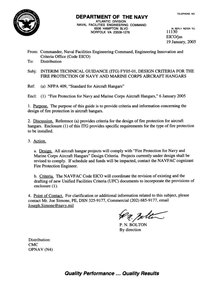
COMLANTFLT (N4) Subj: INTERIM TECHNICAL GUIDANCE (ITG) FY05-01, DESIGN CRITERIA FOR THE FIRE PROTECTION OF NAVY AND MARINE CORPS AIRCRAFT HANGARS COMPACFLT (N4) COMUSNAVEUR COMNAVAIRSYSCOM COMNAVSEASYSCOM COMNAVRESFOR COMNAVREG NORTHEAST COMNAVREG MID-ATLANTIC COMNAVREG SOUTHEAST COMNAVREG FAR EAST COMNAVREG NORTH COMNAVREG NORTHWEST COMNAVREG SOUTHWEST COMNAVREG HAWAII NAVFAC ATLANTIC NORFOLK VA NAVFAC EFD SOUTH CHARLESTON SC NAVFAC EFD SOUTHWEST SAN DIEGO CA NAVFAC PACIFIC PEARL HARBOR HI NAVFAC WASHINGTON DC NAVFAC EFA MED MEDITERRANEAN NAPLES IT NAVFAC MIDWEST GREAT LAKES IL NAVFAC EFA NORTHEAST PHILADELPHIA PA NAVFAC EFA NORTHWEST POULSBO WA ENGFLDACT WEST PWC GUAM PWC JACKSONVILLE NAVFAC MIDLANT NORFOLK VA PWC PENSACOLA PWC SAN DIEGO PWC YOKOSUKA 2 6 January 2005 1-1 PURPOSE. This document provides design criteria for fire protection in Navy and Marine Corps aircraft hangars. 2-1 APPLICATION. This document applies to new or renovated aircraft hangars. Projects currently under design shall be revised to comply. If schedule and funds are impacted, contact the NAVFAC cognizant Fire Protection Engineer. 3-1 REFERENCED PUBLICATIONS: National Fire Protection Association NFPA 409, “Standard for Aircraft Hangars” 4-1 GENERAL REQUIREMENTS: 4-1.1 The requirements of NFPA 409 that are not modified by this document shall apply. All hangars shall be classified as Group I hangars, unless prior approval is obtained from NAVFAC HQ to construct as Group II or Group III hangars. 4-1.2 The type of construction, internal separations, clear space distance requirements around hangars, floors, columns, doors, and other features shall comply with the requirements of Group I hangars in NFPA 409. 4-1.3 When using overhead radiant heat systems, natural gas-fired tube heaters should be specified for the aircraft servicing area. The use of overhead radiant heat systems that utilize any heaters with a flame or glowing element open to the atmosphere in the aircraft servicing area may cause the optical flame detectors to activate when the heaters start up. 4-1.4 Provide a water supply that will support the combined demand of the ceiling sprinkler system, low-level fire suppression system, and the hose stream allowance. 4-1.5 The hangar aircraft storage and servicing area shall be protected with closed-head water only sprinkler system and low-level AFFF system. The closed-head water only sprinkler system can either be wet pipe or preaction sprinkler system. The use of wet pipe or preaction sprinkler system will depend on climate conditions. 4-1.6 Draft curtains shall be provided in accordance with NFPA 409. The draft curtains shall extend down from the roof or ceiling of aircraft storage and servicing areas not less than one-eighth of the height from the floor to roof or ceiling, or to the bottom cord of the truss, which ever is lower. 4-1.7 Provide trench drains in the aircraft storage and servicing area. The trench drains shall be spaced a maximum of 50 feet (15.2 m) center-to-center. The location of the trench drains will depend on the configuration of the hangar. For "Drive-thru" type hangars (see Figure 1), provide ITG FY05-01 1 of 8 19 January 2005 Enclosure (1) trench drains parallel to the hangar bay doors and space them in-between with a spacing not to exceed 50 feet (15.2 m) center-to-center. A trench perpendicular to these trenches may be necessary to route the system piping. For "Pull-in" type hangars (see Figure 2), provide a trench drain in the aircraft storage and servicing area located just inside and parallel to the hangar bay door. Additional trench drains shall be provided perpendicular to the hangar bay door with spacing between trench drains not exceeding 50 feet (15.2 m) center-to-center. 4-1.8 Trench drains shall be sized to account for the flow of the sprinkler system, AFFF system discharge, hose stream allowance, the volume of the pipe, turning radius of the fittings, and allow for maintenance. 4-1.9 Foam concentrate tanks, proportioning equipment and sprinkler control valves shall be located in a room separate from the aircraft servicing area by a minimum of 1-hour fire resistive construction. Flow control valves/proportioners may be located outside of this room in order to minimize the AFFF delivery time to the hangar floor. Equipment rooms shall be configured or sized to provide access for inspection, maintenance, and repair of all equipment. Doors providing direct access to the exterior of the structure shall be provided. Equipment shall be located to permit removal of tanks, bladders, valves, pumps, and motors without the removal of other components. 4-1.10 If piping must be located below the floor line, use concrete trenching with steel grating. Do not install any piping below a concrete slab. Avoid locating piping under paved operational surfaces (taxiways and aircraft parking). 4-1.11 Provide optical flame detection utilizing the triple infrared (IR) flame detectors that are manufactured by Spectrex Inc. (SharpEye Triple IR (IR3) Optical Flame Detector (20/20I)), or Det-Tronics (X3301 Multispectrum IR flame detector). The activation of any two triple IR flame detectors shall activate the low-level AFFF fire suppression system. 4-1.12 The triple IR detectors shall be mounted approximately 8 feet (2.4 m) above the finished floor of the hangar. The specifics for each facility must take into account facility construction, type of aircraft, aircraft configuration and positioning, fixed and mobile equipment within the aircraft servicing area, and all other relevant factors. 4-1.13 The optical flame detectors shall be installed with five feet (1.5 m) of flexible conduit to allow for any minor adjustments during testing or changes in mission of the hangar. 4-1.14 All areas of the aircraft hangar floor shall be visible to a minimum of 3 optical flame detectors. 4-1.15 If a preaction sprinkler system is used, install 160°F (71°C) rate compensated type heat detectors or thermistor type thermal detectors to activate the system. The detectors shall utilize a spacing of 40 feet by 40 feet (12.2 m by 12.2 m) regardless of ceiling height, but shall not exceed their listed spacing (for a ten foot ceiling) without consideration for reduction in spacing. Operation of a single detector shall activate the deluge valve for the preaction sprinkler system. ITG FY05-01 2 of 8 19 January 2005 Enclosure (1) 4-1.16 Provide abort switches that are the "dead-man" type. The abort switch shall be used in conjunction with valves and equipment that will prohibit the discharge of AFFF or water from the low-level fire suppression system, regardless of whether the low-level fire suppression system has been activated. The fire suppression system control/release panel shall supervise the abort switches and their wiring. 4-1.17 The foam concentrate piping shall use stainless steel pipe with roll grooved fittings, welded joints and fittings, or flanged joints and fittings. If using welded joints and fittings, consideration shall be given to the maintenance of the system and provide flanged joints at certain locations to allow for the ease of maintenance. The trim piping on all deluge valves, flow control valves, and alarm check valves shall utilize brass piping. Any concealed concentrate piping shall use welded or flanged fittings. The fittings and gaskets shall be made of EPDM. 4-1.18 A reserve foam tank is only required for systems that use bladder tanks. Note: For remote locations, it is recommended to have a reserve supply of AFFF available on base for refill purposes. 4-1.19 The AFFF concentrate tank(s) shall be provided with spill containment, i.e., provide berm to contain any spill or leak. 4-1.20 Provide manual release stations for activation of the low-level fire suppression systems and the preaction sprinkler systems (if used). Fire alarm manual pull stations and AFFF manual release stations shall be protected (i.e., hard plastic protective covers) from accidental activation. AFFF manual release stations shall be distinctively identified, by color, from the fire alarm manual pull stations. The AFFF manual release stations shall be provided with signage to identify which system(s) will discharge when the release station is activated. 4-1.21 Fire detection and actuation system control panels must be installed in an environmentally controlled area that maintains temperature and humidity in accordance with the manufacturer's listing/approval, but not less than 60F (15C). Ensure that the control panels are not subject to water leakage/runoff from building equipment. 4-1.22 For connections between potable water systems and systems containing foam, provide a reduced-pressure backflow preventer. For calculation purposes, a friction loss of at least 15 psi (104 kPa) across the reduced-pressure backflow preventer or 5 psi (35 kPa) higher than the manufacturer’s listed pressure loss, whichever is greater, shall be calculated. 4-1.23 Hand hose stations shall not be provided. 4-1.24 Provide a listed expansion chamber of appropriate size and pre-charged air pressure to compensate for thermal expansion in the automatic wet pipe sprinkler system in the aircraft storage and service areas. ITG FY05-01 3 of 8 19 January 2005 Enclosure (1) 4-1.25 The water supply shall be evaluated to determine if surge suppressors will be necessary to prevent damage from water hammer. 4-1.26 Provide double basket duplex or wye strainer(s) for the AFFF system. The type of strainer and location of the strainer(s) will be determined by the NAVFAC cognizant Fire Protection Engineer. Strainer baskets shall be stainless steel with a mesh size no greater than 1/16 -inch (1.59 mm). 4-1.27 The flow switch (pressure switch) for the overhead sprinkler system in the aircraft storage and service area shall not cause the low-level fire suppression system to activate. 4-1.28 The control panel for the building fire alarm and releasing panel for the AFFF shall be combined only if more than 75% of the detection devices in the building are for the AFFF system. 4-1.29 Provide separate power disconnects for the fire pumps and foam pumps (if foam pumps are provided). 5-1 LOW-LEVEL FIRE SUPPRESSION SYSTEM 5-1.1 Provide a low-level AFFF system utilizing the Viking Grate Nozzle™, Model GN 200 or equivalent that is acceptable to NAVFAC’s Chief Fire Protection Engineer for this use. The nozzles shall be located in the trench drains with spacing between nozzles not exceeding 25-foot intervals (7.6 m). The distances between grate nozzles and hangar door openings shall be 20 feet (6.1 m). The distances between grate nozzles and walls that separate aircraft storage/servicing area from administrative, shop or similar occupied areas of the hangar shall be 20 feet (6.1 m). These distances are intended to minimize the amount of foam discharged beyond the trenches. 5-1.2 Provide a supply of 3% AFFF concentrate meeting Military Specification MIL-F24385F, Fire Extinguishing Agent, Aqueous Film-Forming Foam (AFFF) Liquid Concentrate, for Fresh and Seawater, to support a 10-minute discharge at the water flow rate based on the supply calculation method and 3.9% concentration. 5-1.3 The grate nozzle pressure shall be maintained at 40 psig to 45 psig (275 kPa to 310 kPa) for all nozzles. The use of flow control valves for this application is required. The flow control valves shall be equipped with the automatic re-closing feature and speed control settings. 5-1.4 The AFFF delivery time from time of detection to discharge from the most remote nozzle shall not exceed 30 seconds. 5-1.5 The foam proportioner shall be provided with a by-pass in order to facilitate flushing of the system (see Figure 3). 5-1.6 Each foam proportioner shall be provided with a test connection (see Figure 3) to allow for the connection of hose lines in order to test the foam proportioners. Provide a ITG FY05-01 4 of 8 19 January 2005 Enclosure (1) supervised control valve in the system piping downstream of the test connection so the system can be isolated when the foam proportioner is tested. This configuration will allow testing of the foam proportioner without flowing foam-water solution throughout the system (see Figure 3). Each test header must be sized for the demand that it serves. 5-1.7 The piping in the trench shall have end caps that are tapped with a valve to allow for draining the piping after it has been activated and attaching a pressure gage for testing purposes. 5-1.8 The low-level AFFF system, including the Grate Nozzle™, shall be flushed prior to any testing and after final acceptance. 5-1.9 For AFFF proportioning systems that utilize foam pumps, a test connection shall be provided to facilitate testing the foam pumps in accordance with NFPA 20. 5-1.10 For testing purposes, the foam system shall be equipped with fittings to accommodate an auxiliary tank of alternate test liquid to determine foam solution flow and foam solution concentration utilizing the conductivity method. 5-1.11 Bladder Tank Systems: The foam system, water and foam concentrate supply lines, shall each be fitted with one 2-inch valved connection to accommodate interconnection of an auxiliary tank containing an alternate test liquid to be used in place of AFFF for proportioning system concentration testing. Installation of the valved connection on the foam concentrate piping shall be at the lowest point and located between the manual and automatic foam concentrate injection valves. 5-1.12 In-Line Balanced Pressure Pump Type Systems: The foam system shall be fitted with two (2) additional 2-inch valved connections on the foam concentrate inlet piping to each foam pump. These connections will be used to interconnect an auxiliary tank containing an alternate test liquid that can be used in place of foam for future proportioning system concentration testing. 5-1.13 The local environmental regulations must be considered to determine the control measures for the discharge of the AFFF. ITG FY05-01 5 of 8 19 January 2005 Enclosure (1) Figure 1 ‘Drive Through’ Type Maintenance Hangar Not to Scale Trenches Spaced at Maximum of 50 ft Intervals Nozzles Spaced at Maximum of 25 ft Intervals Grate Nozzle (Typical) Hangar Doors 20 ft (6.1m) Spacing Hangar Doors 20 ft (6.1m) Spacing 20 ft (6.1m) Spacing ITG FY05-01 6 of 8 6 January 2005 Enclosure (1) Figure 2 ‘Pull In’ Type Maintenance Hangar Not to Scale Trenches Spaced at Maximum of 50 ft Intervals Nozzles Spaced at Maximum of 25 ft Intervals 20 ft (6.1m) Spacing 20 ft (6.1m) Spacing Grate Nozzle (Typical) 20 ft (6.1m) Spacing Hangar Doors ITG FY05-01 7 of 8 6 January 2005 Enclosure (1) To Low-level AFFF Nozzle System By-Pass Test Connection Figure 3 – Low-level AFFF Riser ITG FY05-01 8 of 8 6 January 2005 Enclosure (1)
