Effect of hull gap on pressure distribution under PAR platform
advertisement
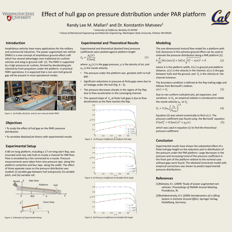
Effect of hull gap on pressure distribution under PAR platform Randy Lee M. 1 Mallari and Dr. Konstantin 2 Matveev 1 University of California, Berkeley CA 94704 2 School of Mechanical Engineering and Materials Engineering, Washington State University, Pullman WA 99164 Introduction Amphibious vehicles have many applications for the military and commercial industries. The power augmented ram vehicle (PARV) is a new concept of amphibious ground-effect craft which has several advantages over traditional air-cushion vehicles and wing-in-ground craft [1]. The PARV is supported by a high-pressure air cushion, formed by decelerating jets injected by front propulsors under the platform. In practical PARV operations, it is expected that a non-zero hull-ground gap will be present in most operational modes. Experimental and Theoretical Results Experimental and theoretical (dashed lines) pressure coefficients were plotted against platform length 𝑝𝑔 𝑥 𝐶𝑝 = 0.5𝜌𝑢𝑛2 Modeling (1) where 𝑝𝑔 𝑥 is the gage pressure, 𝜌 is the density of air, and 𝑢𝑛 is the nozzle velocity. • The pressure under the platform was greatest with no hull gap . • Significant reductions in pressure at finite gaps were due to air leakage under the hull (Fig. 4 – 5). • The pressure decreases sharply in the region of the flap due to flow acceleration in the converging channel. • The upward slope of Cp at finite hull gaps is due to flow deceleration as the flow reaches the flap. The one-dimensional inviscid flow model for a platform with hull clearances in the extreme ground effect can be used to estimate the pressure distribution along a PAR platform [2]. 𝑑 𝑏 ℎ 𝑥 𝑢 𝑥 + 2𝑑 𝑥 𝑈𝑗2 − 𝑢 𝑥 2 = 0 (2) 𝑑𝑥 where 𝑏 is the platform width, ℎ 𝑥 is ground and platform distance, 𝑢 𝑥 is the velocity in the channel, 𝑑(𝑥) is the gap between hulls and the ground, and 𝑈𝑗 is the velocity at the channel entrance. The boundary condition is defined at the flap trailing edge and follows from Bernoulli's relation. 𝑢 𝑐 = 𝑈𝑗 (3) Due to non-uniform turbulent jets, jet expansion, and variations in 𝑈𝑗 , an empirical relation is introduced to relate the nozzle velocity 𝑢𝑛 to 𝑈𝑗 . 0.6 𝑈𝑗 = 5.2𝑢𝑛 0.5 Figure 1. (a) Profile, (b) front, and (c) rear view of model PARV. p C • To correlate idealized jet theory with experimental results. 0 0 which was used in equation (1) to find the theoretical pressure coefficient. d = 0 mm d = 5 mm d = 10 mm 0.1 0.2 0.4 0.6 0.8 1 x/c Figure 3. (i) Pressure Coefficient at Uniform Hull Gap Experimental Setup Conclusion Experimental results have shown the substantial effect of a finite hull gap height on the reduction and re-distribution of the pressure under the PAR platform. Large decreases in the pressure and increasing trend of the pressure coefficient in the front part of the platform relative to the nominal case without gaps were found. The idealized inviscid jet model with empirical corrections was shown to predict experimental pressure distributions. 0.5 p 0.4 C A 80-cm-long platform, including a 17-cm-long stern flap, was mounted onto two side hulls to create a channel for PAR flow. Flow is emulated by a fan connected to a nozzle. Pressure measurements were taken from nine pressure taps along the platform centerline and four taps along the width. The effect of three separate cases on the pressure distribution was studied: (i) variable gap between hull and ground, (ii) variable pitch, and (iii) variable roll. 0.3 0.2 • To study the effect of hull gap on the PARV pressure distribution. 0.3 0.2 = 0o 0.1 = 0.28o = 0.56o 0 0 0.2 0.4 0.6 0.8 1 x/c References Figure 4. (ii) Pressure Coefficient at Variable Pitch Angle [1]Matveev, K.I. (2009) ‘Study of power augmented ram vehicles’, Proceedings of SNAME Annual Meeting, Providence, RI. 0.5 C p 0.4 [2]Rozhdestvensky, K.V. (2000) Aerodynamics of a Lifting System in Extreme Ground Effect, Springer-Verlag, Heidelberg, Germany. 0.3 0.2 = 0o 0.1 = 0.92o = 1.83o 0 0 0.2 0.4 0.6 0.8 x/c Figure 2. Schematic of Experimental Setup (4) Equation (2) was solved numerically to find 𝑢 𝑥 . The pressure coefficient was found using the Bernoulli equation 2 0.5𝜌𝑈𝑗 = 0.5𝜌𝑢 𝑥 2 + 𝑝𝑔 𝑥 (5) 0.4 Objectives 𝑡𝑛 ℎ𝑎𝑣𝑔 2.4 Figure 5. (iii) Pressure Coefficient at Variable Roll Angle 1
