Operational planning in state machines Hans Georg Schaathun Magne Aarset
advertisement
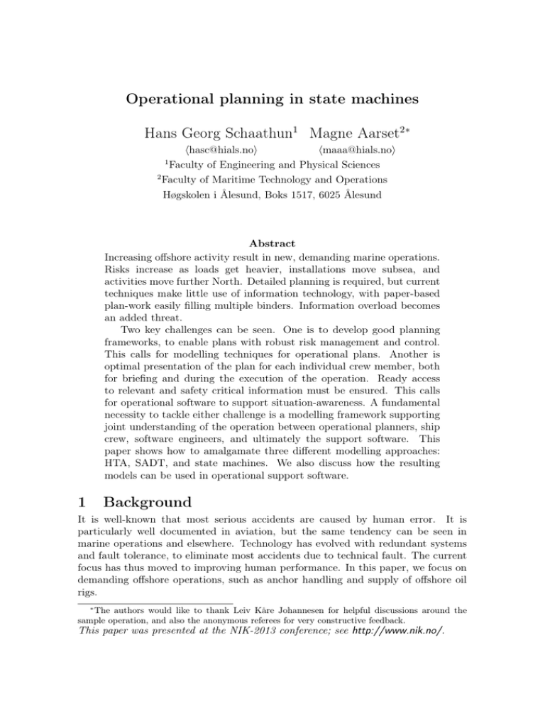
Operational planning in state machines Hans Georg Schaathun1 Magne Aarset2∗ hhasc@hials.noi hmaaa@hials.noi 1 Faculty of Engineering and Physical Sciences 2 Faculty of Maritime Technology and Operations Høgskolen i Ålesund, Boks 1517, 6025 Ålesund Abstract Increasing offshore activity result in new, demanding marine operations. Risks increase as loads get heavier, installations move subsea, and activities move further North. Detailed planning is required, but current techniques make little use of information technology, with paper-based plan-work easily filling multiple binders. Information overload becomes an added threat. Two key challenges can be seen. One is to develop good planning frameworks, to enable plans with robust risk management and control. This calls for modelling techniques for operational plans. Another is optimal presentation of the plan for each individual crew member, both for briefing and during the execution of the operation. Ready access to relevant and safety critical information must be ensured. This calls for operational software to support situation-awareness. A fundamental necessity to tackle either challenge is a modelling framework supporting joint understanding of the operation between operational planners, ship crew, software engineers, and ultimately the support software. This paper shows how to amalgamate three different modelling approaches: HTA, SADT, and state machines. We also discuss how the resulting models can be used in operational support software. 1 Background It is well-known that most serious accidents are caused by human error. It is particularly well documented in aviation, but the same tendency can be seen in marine operations and elsewhere. Technology has evolved with redundant systems and fault tolerance, to eliminate most accidents due to technical fault. The current focus has thus moved to improving human performance. In this paper, we focus on demanding offshore operations, such as anchor handling and supply of offshore oil rigs. ∗ The authors would like to thank Leiv Kåre Johannesen for helpful discussions around the sample operation, and also the anonymous referees for very constructive feedback. This paper was presented at the NIK-2013 conference; see http://www.nik.no/. Situation awareness is a hot topic in human factor research. Situation Awareness Crew members make decisions Perception Projection based on their perception and Comprehension of Elements of Future understanding of the environof Situation of Situation Situation ment, this perception – or situaLevel 1 Level 2 Level 3 tion awareness – progress in different levels (Figure 1). Suboptimal comprehension will lead State of Action Decision to suboptimal, and occasionally Environment fatal, decisions. Perceiving individual pieces of information is straight-forward. Comprehend- Figure 1: Situation-awareness — levels of perception. ing the situation, through the filtering of relevant information from noise, is much harder. In complex and demanding operations, information overload can hinder situation awareness. The information needed by the operational crew include both dynamic information, including the current state of the ship, ship sensors, visual observation, and static information, comprising operational plans, procedures, and legislation. One approach to support and increase situation awareness would be an information system to filter relevant information and visualise and present it in an effective way. Current plan-work and procedures are mainly based on paper (as in Figure 2) or possibly PDF-documents, often a result of months of planning by on-shore engineering teams. Available software is mainly standard office packages, with Microsoft Word as the dominant player. Diagrams and figures may be produced by CAD tools or project management software, without any means to integrate information from different sources in electronic form. The lack of established modelling frameworks makes structuring and machine processing of the plan-work difficult. The need for on-board decision sup- Figure 2: Status quo. Plans and procedures on port software has been recognised by paper. several authors [12, 11, 15]. Several groups and companies focus on integrated bridge designs, where information from different subsystems are accumulated in a single bridge system for coherent presentation. Search and rescue operations has received particular attention, including Glässer et al. [7, 8], who presented a decision support system using sensor data from the ship, and Lijnse et al. [10] who discussed a work-flow management system. Integrating and using relevant static information in the on-board system is still an open problem. This is particularly important for demanding offshore operations which are carefully planned ahead of execution, contrary to search and rescue operations. Some authors have discussed the modelling of the marine operation and on-board tasks, but their objective has mainly been off-line assessment. Embrey et al. [4] studied workload assessment for on-board crew, reviewing a number of modelling and task analysis techniques for this purpose. Others have focused on risk assessment [6] and risk management [9]. Unfortunately, the underlying models and software architecture have not been published. We [13] have previously discussed the modelling of demanding operations, amalgamating modelling techniques from software engineering and from operational planning and human factor research. In this paper, we further extend this work by incorporating a more advanced modelling framework from human factor research, namely SADT, and defining the concept of roles to support tailored presentation for individual crew members. As before, our main contribution is to develop a language which can be shared by the different disciplines involved, including software engineering, operational planning, risk management, and offshore vessel crew. This is achieved by building on familiar concepts in each discipline, highlighting corresponding terms, and establish the links with other, familiar frameworks within each discipline. 2 Modelling Background Most areas of science and engineering have a concept of modelling, without necessarily having a shared view of what constitutes a model, or what makes a model relevant or appropriate. What we believe is the essence of modelling across disciplines, is captured by the following quote by Bran Selic [14]: [An engineering model is] «a selective representation of some system that captures accurately and concisely all of its essential properties of interest for a given set of concerns.» We observe the focus on why we need modelling: Models aid the understanding of complex systems. The appearance of a model (text, diagrams, formulæ) is irrelevant. Two particular features are key to support understanding. Firstly, the model is a representation of a system, and we can understand the system by studying the model. Secondly, the representation is selective and relative to a given set of concerns. Anything which is not needed for the task at hand should be shaved away using Ockham’s razor. Thus, different models of the same object may be needed for different kinds of analysis. We are interested in two separate modelling domains, namely software and operations. Software engineering has a rich literature on modelling, including formal languages, metamodelling, and automated model transforms. Most well known is the Unified Modelling Language (UML), which is not just one language but rather a family of languages aiming to model different aspects (or views) of the system. As a standard, UML has developed a very complex syntax to allow detailed representation of models, but most of the modelling techniques promoted by UML are well-known in other contexts and fully usable with a much simpler syntax. Although differences may be identified between marine operations and business processes, we can benefit from the rich literature on business and process modelling. A classic is the Structured Analysis and Design Technique (SADT) [2] and the more current IDEF0 standard building thereon. A little work has been done to link modelling frameworks from different disciplines. In particular, the human-computer interaction (HCI) community has made some progress connecting human performance models to software architecture. More formally, Bastide [3] integrates task models and use-case models on the metamodel level. 3 Introduction to relevant modelling techniques We will take a rather informal view of the modelling frameworks HTA, SADT, and state machines. We focus on relating the fundamental structure of the frameworks, rather than syntactic and semantic details, and refer the reader to other sources for more details. Hierarchical Task Analysis We will start our discussion with Hierarchical Task Analysis (HTA), which is wellknown among operational experts. Emerged around 1970 in psychology and human performance research, it is still popular. The technique is simple and flexible with core ideas carrying over to the more formal approaches to be discussed later. A good introduction is given by Stanton [16]. HTA is an iterative technique. At the first level, the operation is viewed as a single task. Any task can be broken into subtasks with an increasing level of detail. Each task and subtask should be described in terms of its goal, with an objective statement of its intended outcome. The relationship between a task and its subtasks is that of set inclusion; in a tree-like structure. There may or may not be an annotated procedure describing how to process the subtasks. There is no limit to the number of levels in the HTA tree; it is merely a question of the desired level of detail. A trivial task should not be subdivided just for the sake of it. Some branches may require more levels than others. Little formalism is offered by HTA, making it very flexible and intuitive to use. Tasks may be elaborated by free-form descriptions. For the low-level tasks, this could be an instruction sheet comprising text and figures. High-level tasks, frequently require no more than a sentence to say whether subtasks are to be executed in sequence, in arbitrary order, or in some specific arrangement (such as loops or conditionals). Structured Analysis and Design Technique Another classic in operational and process modelling is the Structured Analysis and Design Technique (SADT). It is possibly better known as IDEF0, which standardised the syntax and semantics in 1981. We will focus on the approach and its key concepts, rather than syntactic and semantic detail, and will therefore refer to SADT, which is discussed with some variations in a number of textbooks. Tasks in HTA correspond to activity boxes in SADT. As in HTA, activity boxes are hierarchically subdivided into subactivities. SADT focuses on information flow and resource dependencies between activity boxes. As a running example throughout the paper, we will take a supply operation, i.e. the delivery of supplies to an offshore rig. At the top level, the complete operation forms a single SADT activity box as shown in Figure 3. The activity box is labelled with the task, and furnished with four different kinds of arrows. Input to the activity is represented by one or more arrows from the left, representing data or material which is consumed or modified through the activity. Output is represented by one Operation: Platform Supply Procedures Weather Corporate Culture Complete supply operation Order Ship Rig Acknowledgement Base Figure 3: Sample operation in SADT, top level Activity: Complete Supply Operation Receive and process order Acknowledgement Loading Base Transit Base Lift/Pump Ship Ship Return Order Ship Rig Ship Figure 4: Sample operation in SADT, level 1 or more arrows to the right. The output of one activity box may be the input of another. Arrows from above are called controls and may affect the activity in various ways, whether by accident or by design. Controls are not modified by the activity, at least not directly, and thus several activities may use the same control independently. Detailed discussion of controls is out of scope for this paper. Arrows from below represent resources, which are utilised but not consumed by the activity. This includes both personnel and equipment. In the example, at the coarse level of Figure 3, we include the crew with the ship, rig, and base. The ship and its crew operate as a unit, and will not be separated during normal execution of the operation. Any activity box can, recursively, be elaborated as an SADT diagram consisting of multiple SADT boxes. See for instance Figure 4 where we have elaborated the operation from Figure 3. We think of Figure 4 as zooming in on the top level activity box. We note that every resource in the top level activity box also occur in the Level 1 diagram, in at least one subactivity. Likewise, the input and output from the top level have to reoccur at the next level, and they are the only input/output arrows which are connected at only one end. Other input/output arrows (internal arrows) connect two subactivities. Unlike HTA, the arrows in SADT imply dependencies between subtasks and sequencing constraints are made explicit. For simplicity, we have suppressed the controls, but they would follow the same principle: the same controls must be found in the parent activity and some subactivity. As in HTA, the activity boxes may be annotated with free-form instructions, to give the users a complete instruction. The value of annotations should not be underestimated. The formal modelling is used to aiding understanding by structuring the plan-work. Overdone, it would cloud understanding, and many details are best described in free-form. There are two distinct variations of SADT seen in existing applications. Even though the distinction has not, to our knowledge, been made explicit in existing literature, it is both important and easy to spot from a computer science viewpoint. We will call them functional and procedural SADT respectively. In functional SADT, we view the activity boxes as functions. The key features are seen in the output as a function of the input, resources, and controls. This appears to be the classic version in the literature and the most common intent in applications. Production processes are typically described well in functional SADT, with raw materials as input and product as output. Such processes will often be pipelined. Using different resources for different activity boxes, they can work concurrently on different batches of the product. Procedural SADT is used in operational models, for instance in avionics [1]. Here, the input/output between activity boxes are signals or commands, indicating that an activity is complete and a new activity can start. No materials are passed between the aircraft pilot and control. Instead, the activities are concerned with the state of a resource, namely the aircraft, and the input/output are assertions such as ‘ready for takeoff’. State Machines A fundamental modelling technique in computer and software engineering is that of a state machine. We showed in [13] how HTA models can be translated into state machines and used as the basis software to support situation-awareness. Definition 1 A state machine is a directed graph, with nodes called states and edges called transitions. Each transition is labelled with a Boolean condition. The states can be thought of as mutually exclusive situations, and the transitions represent the event where the system is brought from one state to another, which happens when the label of the transition is true. The UML concept of state machines has added two additional features to the traditional definition. Firstly, we allow hierarchical state machines. In the same way that we can ‘zoom in’ on an SADT activity box to see an elaborated SADT diagram, we can ‘zoom in’ on a state to see a new, more detailed state machine. We call the high-level state a superstate, and the states of the lower level state machine are called substates. The superstate can be viewed as the union of all its substates. The other new idea in UML state machines is orthogonal regions, which allow parallel states. A superstate can be divided into multiple regions, each with its own state machine with substates. The orthogonal regions are ‘processed’ in parallel, and state transitions happen independently in each region. The total state space is the Cartesian product of the state spaces for each region. From SADT to State Machines Many instances of SADT can be read almost directly as state machines, especially in the case of procedural SADT. The output/input arrows in SADT introduce dependencies between activities. An activity can only start once the input has been received from the preceding activity, making the activities mutually exclusive. The output/input arrows can be seen as state transitions, and the activity boxes as states. For instance, the top level SADT activity box, disregarding resources and controls, become a state machine when we connect the input arrow to a state called ‘not started’, and the output arrow to a ‘completed’ state. Such entry and exit states are sometimes called pseudo-states and marked with special symbols in UML. The resources from SADT must be added to the state machine model. It can be formalised as a relation R ⊂ S × R where S is the state space and R is the set of resources. Many operations are strictly sequential, due to safety and transparency requirements. This is for instance the case in Figure 4. In such cases, the translation from SADT to state machines is trivial. There are other cases, where the SADT activity boxes should be undertaken in parallel. This may happen where one SADT activity box provides the input to two or more activity boxes. If there are no other dependencies, the corresponding activities may run in parallel. In the state machine model, such parallel activities must be collected in one superstate with parallel regions. Thus, we may have to introduce an extra level in the state machine model, compared to SADT, to fit the parallel regions. This has the advantage of making the parallelism very explicit, clarifying the SADT model. Often, each region will have only a single state apart from entry and exit pseudostates, corresponding to the activity box from SADT. Parallel activities are well justified when they do not share any resources. Then each resource will only need to be aware of a single activity box or a single state in the state machine at any point in time. In theory, SADT would allow us to express a model where one resource is engaged in multiple parallel activities, but it would give no information about how to share the resource between the activities. If the resource is a crew member, he would have to keep both activities in mind with no help from the model, leading to unnecessary cognitive strain. Therefore, we assume that parallel activities in useful models will not share any resources. Consequently, in the state machine model, each orthogonal region within a superstate will have non-intersecting resources. 4 Models of Marine Operations We have seen how main principles of different modelling frameworks can be mapped to each other, and briefly discussed how modelling frameworks can be restricted or augmented with very simple means to facilitate translation and avoid certain under-defined cases. Understanding situation Our main objective is to capture the idea of situation awareness. In human performance research, a situation denotes the complete context (state of environment) that a human is relating to at a point in time. There are, of course, no limits to the amount of detail which can be included in the notion of a situation. When we model the operation, we will need to limit our scope, to get a well-defined space of possible situations. A hot topic in software engineering is that of context awareness. This may appear related to situation awareness, but the differences turn out to be significant. A context is usually defined as a fixed environment, independent of the user, which any user can enter or leave. A context could for instance be a shopping mall, where the software tailors the view to include available promotions, local restaurants, etc. Any number of users may enter the same context without interacting or changing it. Our notion of situation is subjective and highly dependent on each user present. If a deck officer suddenly were to leave the ship, a new situation would arise for everyone involved. In contrast, a situation seems to be closely related to an activity box in SADT or corresponding state in a state machine model. The current state defines what has been completed and what has to be done next. These are crucial pieces of information for the crew involved. The definition of state implies that each role is concerned with only a single state at a time. The operational plan usually defines a number of key indicators which have to be monitored, typically performance or safety parameters such as fuel consumption or wind speed. Critical thresholds may be set to trigger alarm situations. All key indicators are not necessarily relevant at every stage of the operation, and thus they may change depending on the current state in the model. These key indicators is the second crucial piece for situation awareness. Modelling resources and roles A key element in our vision is to give tailor-made presentations for each crew member. This is a well-understood problem in software engineering. We usually consider roles rather than individuals (e.g crew members). A role can be defined as a set of rights and responsibilities, and a physical person can have multiple roles, and several people may have the same role. The software should respond to the role, rather than the identity, of the user. In SADT, the crew members are a special case of resources, and they are recorded in the model by arrows from below in the different activity boxes. Thus, SADT already provides some information as to what information will be significant for each crew member. In complex marine operations, the resources can be hierarchically organised. In our example we included crew with each of the ship, rig, and base. At lower levels, with more detail, individual members of the ship crew would be assigned to different activity boxes. Thus we view the resources in the SADT diagram as subsets, rather than elements, of the universe of resources. The significance of a role in a marine operation is not obvious. The role of captain is permanent (also when the captain is asleep). The officer of the watch is a transient role, typically held by the captain during critical phases and another officer most of the time. Aiming to support situation awareness and limit cognitive strain, each crew member should have only one role at a time, so that the software can manage the complete set of information required. Focusing on critical phases of the operation, where the need for new support tools is the greatest, we define a role, which appears as SADT resources, as the set of responsibilities and rights assigned to a given crew member. This works because the operational plan will assign each crew member to a specific post, with rather detailed descriptions of duties. The concept of roles must be refined in the future, to allow crew members to change post during longer missions, while still allowing each crew member to focus on only a single role at a time. Modelling undesirable situations So far, we have assumed that the operation goes according to plan, and there is only one possible successor state whenever one state is complete. In reality, accidents do happen, and contingency planning is essential. Each contingency plan consist of a set of conditions defining when it comes into effect, and a ‘recovery operation’ aiming to return to a safe state, either to continue the operation or to abort. Contingency planning is not explicitly supported in SADT or HTA, but the contingency conditions may be defined in the free-form activity description, with a cross-reference to the recovery operation, which itself can be modelled using SADT or HTA. A good reason to do it this way, is that contingency activities would quickly clutter an SADT diagram. Contingency planning is very easy to model in the state machine. For each contingency plan, we add a state corresponding to the situation(s) where the plan comes into effect. Transitions into this state are labelled with the contingency conditions. UML even provides convenient notation for contingencies which can occur in any substate and cause early transition from the superstate. An SADT model of the contingency plan can then be translated into substates of the contingency superstate. Typically, the contingency conditions are defined in terms of key indicators. We categorise the states with a traffic light scheme. Green represent normal, planned states. Contingency states are coloured amber if we aim to recover the operation, or red if we aim to abort. A fundamental concept in operational plans is stop criteria, i.e. conditions where the operation must be aborted. In the state machine model, this specifies a transition into a red state. We can formalise the definition as follows. Definition 2 A stop criterion is defined as the label of some transition from an amber or green state into a red one. 5 Software The main vision behind this work is an on-board information system to enhance situation awareness. The idea is to give each crew member (role) a presentation of the most relevant and safety critical information, tailored both to the given role and to the current situation, as determined by the state in the operation plan. The proposed software architecture is depicted in Figure 5, using a typical multitier framework. The Static Model Layer handles the operational plan and associated pre-authored information the using modelling framework as described. This includes persistent storage and import from other software such as an editor, exemplified here by an SQL database and an XML file, respectively. The second layer provides the situation awareness, keeping track of the current state according to the static model. It includes communications with other on-board systems, sensors in particular, to access dynamic situation-relevant information. Presentation ... Captain’s View Engine view Gunner’s view Role-aware Logic ... Engine chief Captain Gunner Situation-aware Middleware Log SQL DB Dynamic State Sensor Services Static model layer XML parser State Model Sensors XML file Figure 5: Software architecture View Control Role State Transition Conditions Dynamic Data Figure 6: Architecture for the state aware logic (situation aware middleware). It will monitor key indicators, stop criteria, and transition conditions. Note that the situation aware layer only needs read access to sensors and other on-board systems, so that interference is limited. The log is a suggested feature, which could automatically record task completion and state transitions with time stamps. This could be a dedicated service for this system, or, if write access is granted, the logging data may be fed to another on-board system. The role-aware logic contains modules for each supported role, managing the information relevant for that particular role, based on information retrieved from the situation-aware layer. Each role-specific module in the role-aware logic is mirrored by a module in the presentation layer on top, providing a user-friendly presentation of the relevant information. The role-specific views need to take into account not only the interface to the corresponding role-aware module, but also the available equipment to view the information. Some roles may have large, fix-mounted screens, while others have portable, pocket-size screens. The more detailed design is rather straight-forward, using standard design principles with low coupling and high cohesion. Design patterns [5] provide a structured and standardised approach to support the key features in the architecture. A model-view-controller (MVC) pattern is used. The model is complex, comprising several modules in the role- and state-aware layers. A simple outline is given in Figure 6, considering a single role only. The State module keeps track of the current state at any point in time, and provides access to relevant key indicators and other dynamic objects. The Role module filters the information for the given role. State transitions are controlled via Transition Condition objects which implement the Specification pattern to allow composite conditions (and, or). Conditions may change either as a result of user control or as a result of dynamic data (e.g. sensor data). Both the Transition Conditions, the State, Role, and View need to implement the Observer pattern to detect state changes. A prototype demonstrating the core ideas was discussed in [13], and has since been extended. Page constraints prevent us from discussing it here. We have glossed over one important question, namely the balance between manual and automatic control. It has been pointed out [10] that the absolute authority in marine operations rest with the commanding officer. The decision to execute the next task or enter a contingency plan has to be made by a human decision maker. Hence, such state transitions should be triggered by a command from the captain, and not by an automated system. This does not change the fact that stop criteria and other transition conditions should be monitored and detected by the system. It merely means that the system should alert the relevant decision maker to the changing situation and recommend a decision. This may be handled at a lower level of the hierarchical model, by automatic state transitions between substates in a region associated with the captain only. More work is needed to get all the details in place. 6 Conclusions and open problems Our main contribution is a modelling framework supporting communication and shared understanding between ship officers, operational planners, software engineers, and operational analysts. This is the first step towards effective, computer aided presentation of plan-work. A software architecture and prototype provides a proof of concept, demonstrating the feasibility of the approach. The modelling framework allow us to model plans in a machine processable way. Important problems remain open, both on the modelling side and the implementation side. The most important project to undertake is case studies, to test and evaluate the modelling framework on real demanding marine operations. This is necessary to verify its applicability and identify required improvements, and it will give information about limitations and scalability. We will also need a formalisation of the modelling framework. In terms of implementation, we have focused on the business logic and model management. Good presentation and visualisation of information remains an open problem. We need a better understanding of the work situation and information needs of the ship crew. Based on such an understanding, a new user interface must be built and evaluated. The user interface is the means to support situation awareness, and it has to be very well designed to succeed. The proposed modelling framework is not limited to the proposed on-board software. Individualised presentation and visualisation of the plan would be very helpful for the captain briefing his crew. A model editor would also be a useful tool in operation planning, and the framework could be extended to incorporate risk, for the purpose of risk assessment and risk management. There are good reasons to prioritise these applications before the proposed on-board system, as they may prove easier to realise in the short term, both in terms of implementation and adoptability. The solutions to the different open problems must be drawn from widely different disciplines: nautical studies, computer science, and human-computer interaction. We hope that the present work will support the necessary interdisciplinary collaboration to realise the vision in due course. References [1] Magne V. Aarset. Risk management. Forsikringsakademiet, 1999. [2] Magne V. Aarset. Kriseledelse. Fagbokforlaget, 2010. [3] Rémi Bastide. An integration of task and use-case meta-models. In Julie A. Jacko, editor, HCI (1), volume 5610 of Lecture Notes in Computer Science, pages 579–586. Springer, 2009. [4] David Embrey, Claire Blackett, Philip Marsden, and Jim Peachey. Development of a human cognitive workload assessment tool. Technical report, Human Reliability Associates Ltd., July 2006. MCA Final Report. [5] Erich Gamma, Richard Helm, Ralph Johnson, and John Vlissides. Design Patterns. AddisonWesley, Boston, MA, January 1995. [6] B Gauss, M Rötting, and D Kersandt. Naridas – evaluation of a risk assessment system for the ship’s bridge. In Human Factors in Shop Design, Safety and Operation. RINA - The Royal Institution of Naval Architects. International Conference., March 2007. London, UK. [7] Uwe Glässer, Piper Jackson, Ali Khalili Araghi, and Hamed Yaghoubi Shahir. Intelligent decision support for marine safety and security operations. In Intelligence and Security Informatics (ISI), 2010 IEEE International Conference on, pages 101 –107, May 2010. [8] Uwe Glässer, Piper Jackson, Ali Khalili Araghi, Hans Wehn, and Hamed Yaghoubi Shahir. A collaborative decision support model for marine safety and security operations. In Mike Hinchey, Bernd Kleinjohann, Lisa Kleinjohann, Peter A. Lindsay, Franz J. Rammig, Jon Timmis, and Marilyn Wolf, editors, Distributed, Parallel and Biologically Inspired Systems, volume 329 of IFIP Advances in Information and Communication Technology, pages 266–277. Springer Berlin Heidelberg, 2010. [9] Hans Hederström, Diethard Kersandt, and Burkhard Müller. Task-oriented structure of the navigation process and quality control of its properties by a nautical task management monitor (ntmm). European Journal of Navigation, 10(3), December 2012. [10] Bas Lijnse, Jan Martin Jansen, Ruud Nanne, and Rinus Plasmeijer. Capturing the netherlands coast guard’s SAR workflow with iTasks. In David Mendonca and Julie Dugdale, editors, Proceedings of the 8th International Conference on Information Systems for Crisis Response and Management, ISCRAM, May 2011. [11] Lee A. Luft, Larry Anderson, and Frank Cassidy. Nmea 2000 a digital interface for the 21st century. In Institute of Navigation Technical Meeting, January 2002. [12] Margareta Lützhöft. The technology is great when it works. PhD thesis, 2004. [13] Hans Georg Schaathun, Magne Aarset, Runar Ostnes, and Robert Rylander. Hierarchical task analysis, situation-awareness and support software. In Webjørn Rekdalsbakken, Robin T. Bye, and Houxiang Zhan, editors, 27th European Conference on Modelling and Simulation, pages 184+. European Council for Modelling and Simulation, 2013. [14] Bran Selić. Abstraction patterns in model-based engineering, February 2011. Keynote slides from ModProd 2011 at http://www.modprod.liu.se/MODPROD2011?l=en. [15] Steve Spitzer, Lee A. Luft, and David Morchhauser. Nmea 2000, past, present and future. In RTCM Annual Assembly Meeting and Conference, May 2009. [16] Neville A. Stanton. Hierarchical task analysis: Developments, applications, and extensions. Applied Ergonomics, 37(1):55 – 79, 2006. Special Issue: Fundamental Reviews.
