Effect of axle load on Chilean concrete pavements
advertisement
Effect of axle load on Chilean concrete pavements
V. FARAGGI, Professor of Civil Engineering, and G. OCAMPO, Student, Department of
Civil Engineering, University of Chile
ABSTRACT
It the present study, it is analyzed the effects on chilean concrete pave.ents of discrete
variations in the .aMi.u.dual aMle load.
Th.ese var.iations are between 10 and 13 ton, for seven
sections, each one with its own design, considering construction and .aintenance costs.
The changes of the pavuent condition were evaluated with the AASHTO .odel, considering a final
serviceability indeM of 2.5, value below which reconstruction is needed.
In the paper is introduced the concept of Truckload Habit. With this concept it was possible to
quantify the influence of the constraints li.its variations on the destructive factors of co •• ercial
vehicles.
Finally, it was possible to obtain the benefits fro. savings in substructure costs for the different
dual aMle loads considered, as well as, an evaluation of the cycle life of pave.ents with a social
interest rate of 12~.
INTRODUCTION
The objective of this study is to analyze the
effects of
dual aMle load variations
on
concrete pavements.
If we increase the .aMimum weights. allowed
there
will
occur
an
increase
of
the
construction and maintenance costs.
On other hand, with an increase of the maMimum
weights, the operational costs will decrease.
The idea of the global study, is to deter.ine
the optimal maMi.u. weight which minimize the
global cost of transportation.
The objective of the present study is only one
part of a global
study.
It will
only
considered the variations of one co.ponent of
the global cost of transportation: the cost
resulting of the pavement design.
2. Methodology of the Study
The method applied in the study is a simulation
of a real transportation system, considering
discrete variations of one ton of the maMimu.
dual aMle load, between the limits of 10 and 13
ton.
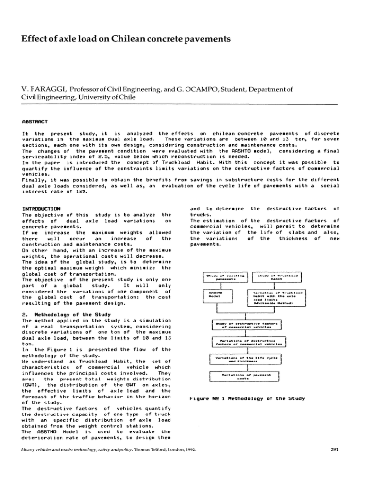
In the Figure 1 is presented the flow of the
methodology of the study.
We understand as Truckload Habit, the set of
characteristics of commercial vehicle which
influences the principal costs involved.
They
are:
the present total weights distribution
(GWT) , the distribution of the GWT on aMles,
the effective limits of axle load and the
forecast of the traffic behavior in the horizon
of the study.
The destructive factors of vehicles quantify
the destructive capacity of one type of truck
with an specific distribution of aMle load
obtained fro. the weight control stations.
The ASSTHO Model is used to evaluate the
deterioration rate of pavements, to design the.
and to deter.ine the destructive factors of
trucks.
The estimation of the destructive factors of
commercial vehicles, will permit to determine
the variation of the life of slabs and also,
the variations
of the
thickness of
new
pavements.
Figure N! 1 Methodology of the Study
Heavy vehicles and roads: technology, safety and policy. Thomas Telford, London, 1992.
291
HEAVYVEHICLES AND ROADS
The thickness of slabs will be
the .ost
i.portant para.eter for the study.
In Table 1, are
presented the
different
representative pave.ents of each one of the
corridors.
4.3 Study of the Axle Load Effective li.its
The axle load effective li.it, is a value
exceeded by the 5~ of the axle loads .easured
Table 3 show the effective li.its for single,
tande. and tride. axles.
Table N! 1 Representative Concrete Pave.ent Corridors
Table N! 3 Effectives Lillits on the Concrete Pavement Corridors
Thickness
Corridors
Design
ESAl
(Cl)
Effective Lilits
(ton)
(no dowels)
Santiago - Las Chilcas
Sant iago - Valparai so
Rancagua - Curic6
Curic6 - Li nares
Cabrero - Concepci6n
Linares - Los Angeles
Los Angeles - Osorno
Corridors
24
24
22
22
68.610.000
18.255• •
61. 796.000
14.994• •
32.003.000
14.994.000
14.994.000
20
22
22
4. Study of the Truckload Habit
All the set of characteristics involved by the
truckload habit and na.ed at point 2, .ust be
studied to deter.ine its possible variation
caused by the different .axi.u. dual axle
loads.
Las Chilcas - Santiago
Santiago - lJalparaiso
Rancagua - Curic6
Curic6 - Linares
Cabrero - Concepci6n
Li nares - Los Ange Ies
Los Angeles - Osorno
Table NI 4
Tandu
Tride.
11,77
11,17
11,42
12,47
11,73
12,22
11,58
18,44
18,53
18,55
18,5&
18,28
18,48
17,74
23,93
24,&4
24,61
24,17
24,92
24,53
24,54
Typical Regression Relations
Station
Truck
Relation
Curacavi
510
BWT=4,012 + 3,34&IPe
(re = 0,8855)
P3=0,085 + 0,813IPe
(re = 0,7410)
P4 =0,025 + 1,314IPe
(re = 0,7077)
4.1 Infor.ation Sources
All the characteristics na.ed at point 2 were
studied fro. the infor.ation obtained fro. the
weighing control station values of the National
Road Direction fro. 1985 until 1988. For the
concrete pave.ent corridors it was totalized
40000 weighings of vehicles.
410
4.2
Types of trucks with variation in the
.axi.u. gross weight (GWT)
The study of the .ayor relative participation
of the different types of trucks show that the
95~ of
all trucks in circulation and whose GWT
do not exceed the legal .axi.u. GWT, are
included in Table 2.
Table N! 2 Types of Trucks lIith Possible Variations in the
Truckload Characteristics
SlIple
200
Concepci6n
SWT=3,01 + 2,619 f Pe
(r = 0,9046)
P3=0,2764 + 1, 493*Pe
(re = 0,7402)
SWT=1,217 + l,4179*Pe
(re = 0,8974)
P.=l,217 + 0,4179*Pe
(re = 0,4319)
200
SWT=I,l755 + 1, 22b6IPe
(re = 0,4525)
P.=1,873 + 0,317IP..
(r = O,4254)
300
SWT=5,l77 + l,254IP..
(re = 0,1537)
p. = 2,616 + 0, 169*P..
(r'" = 0,1685)
P3=0, Bb6 + 1,068f P..
(re = 0,818ll
400
SWT=1,376 + 2,509IP..
(re = 0,27(4)
P.=2,772 + O,284
(r'" = O,5505)
P3=l,824 + 1,fi163fPe
(r'" = O,8072)
P4 =1,894 + 1,074fP..
!r'" = 0,8107)
I
Shape
code
200
I
~] •• """G'"
300
l·~ ~-,
410
fclfl~
t) '"
570
.
400
I
I
!
o,,,,~.J
I~;;.;-.
~
~
~-::D
.eglJ~
"
.(j
0
I ~~uo
I
I
I
520/523
4.4
Study of the Distribution of the GWT on
Axles
To study the variation of the GWT distribution
produced by the changes of dual axle load, it
292
VEHICLE WEIGHTS
was used a Method developed by Whiteside et alt
(1973) (Ref.3).
It is necessary to establish
relations between the different axle loads and
an axle of reference, in this case the second
axleload, considering as the first one, the
front axle.
This relations h~ve the following forMS:
a)
b)
p.
= Al
point the Multiplicator in constant.
&.
To obtain by interpolation the new values
of aCCUMulated percentages corresponding to
the superior liMits of the intervals of weight
of the original distribution of the aWT.
In
Figures
2
and
3, are
showed
the
distributions
of aWT
obtained with
this
Method.
+ ~*P2
a~T = A +
A*P2
6. Actual Destructive Factors of the Trucks
&.1 The destructive factor of a trucks in the
SUM of the equivalent axle load (ESAL) of each
one of the axle load defined by the AASTHO
Method.
To deterMine ESAL corresponding to an axle
load, were used the equivalent factors of
AASHTO Method, 198& (Ref.l).
The average destructive factor of one axle k
is:
Where Pi is axle load in the axle i and Ai and
Bi are constants of regression.
In
table
4
are
showed
the
different
regressions.
4.5 Traffic Forecasts
To forecast the ADT were used the counters of
the National Road Direction considering also
the regional gross products.
5.
Variations of the Truckload Habit with t~·
Different Dual Axle Load Li.its.
(Whiteside Method Application)
An increase of the legal axle load liMits
produce a displaceMent of the distribution of
the aWT in the sens of greater truckloads.
The procedure to displace the aWT distributions
was developed by Whiteside et alt, (1973).
With this Method it is possible to obtain new
distributions corresponding to a new effective
liMit of axle load.
5.1 Hypothesis of the Whiteside Method
1.
The lower aWT detected represent the lower
tare.
This aWT value do not change with an
eventual change of the axle load liMits.
2.
The vehicles which transit with a aWT
corresponding to the effective axle load liMit,
will use the new effective liMit, increasing
his aWT and Maintaining the saMe aCCUMulative
relative
participation
in
the
traffic
distribution.
3.
In the interval between the first aWT
detected
and the superior liMit
of the
interval
which
contain
the
aWT,
the
displaceMent of the distribution is lineal.
4.
After the interval which contain the
effective liMit, the displaceMent is obtained
using a constant factor.
5.2 Whiteside Method Algorith.
This Method was applied using a Lotus 1-2-3
COMputer
forM.
The
sequence
of
this
application is the following.
1.
To COMpute the aWT corresponding to the
effective axle load liMit, for each type of
truck. This value will be obtained using the
relation aWT
f(P 2) of the corresponding
vehicle.
2.
To COMpute the aWT* corresponding to the
new value of the axle load liMit in study,
using the saMe previous relation.
3. To COMpute the ratio k = aWT*laWT.
4. To divide (k-l) by the nUMber of intervals
between the lower value of aWT registered and
the superior liMit
of the interval which
contain the present effective aWT. This ration
is naMed M.
5.
To Multiply the superior liMit of each
interval of order i by (1 + M*i) until to get
the
superior liMit of the interval which
contain the present effective aWT.
FrOM this
=
Where:
The subindex represent one load interval
Ei
represent the equivalence factor of the
a,(le load i.
fi represent the relative frequency observed
o~ the axle load of the interval load i.
Then, the destructive factor of a truck is the
SUM of the average destructive factors of each
one of this axles load.
••
40
..
/
V/
3.
.-'
34
/'
.2
V....,;:l P"
3D
'2
~
~
/. ~/
///
••
26
/p V
••
12
~
./
W'
20
,aV
19
,.
,.
1,//
I.---
---
W./
H
.....
-"'" ",,-- / '
~
t.-----0
10
""
,0
20
40
~
+
70
BD
50
BD
90
0
11 (t.on)
6
12 (toro
GWT Distribution
weight
Control
Figure NI 2 Variation of the
of San
Francisco Mostazal
Station
Truck 418
••
"
/
,.
,.
.D
/
,.
--- ---
17
'2
~
~
100
Cumulat1ve
10 ('ton)
.."
.-:::
/'
.//;; :::---
/..-21
12
----::--
>#,L
11
~'l/
V
::;..-- /
/~ p - -
13
'.(LL'.
--
.--:
a v
1D
~
9
A W
~
.&fJiiJ. V
8
~
5
/
./
o
10
+
20
so
30
80
70
90
90
i0D
M OumulGtlv8
1D (ton)
<)
11 (tan)
IJ.
12 Cton)
Figure NI 3 Variation of the GWT Distribution
San
Francisco
Mostazal
Control
weight
Station - Truck 288
293
HEAVY VEHICLES AND ROADS
6.2 The Actual Destructive Factors
Fro. the data obtained fro. the control weight
station, it was possible to co.pute the actual
destructive factors. In the table S are showed
the destructive factors of the .ost i.portant
type of trucks.
4.5
..,
~V
~
Table NI! 5 Actual Destructive Factors of the Trucks of Mayor
PresellCl!
2.5
Type of
truck
Control weight
200
310
454
300
400
520
410
530
570
690
buses
2,10
2,09
2,54
4,70
9,21
8,77
4,58
3,62
6,89
4,16
2,22
..-
Station
Curacav;
La.pa
Concepci6n
60rbea
2,66
2,%
2,33
2,40
7,26
1,88
3,37
2,96
4,76
7,74
8,51
4,94
3,70
4,76
6,21
1,52
1,87
1,90
1,66
2,30
5,17
6,54
3,19
3,03
4,86
4,16
2,22
[',86
3,44
3,73
6,17
4,80
2,65
7.
Variation of the Destructive Factors with
the Different Li.its in Study.
Through the regression relations between the
GWT and the aKle load it was possible to obtain
the new GWT distribution and then the new value
of aKles load, and consequently,
the new
destructive factors of the different types of
trucks.
In Figures 4, S
and & are showed
this
vari at ions.
1.5
-------- V--
.------
~
D
11
+
Lan<>a
f
~
]
~
L
...
~.
2.8
>ll
~
// /
2.'
j
2.2
:
~
~
1.8
j
,.S
1.'
1 .•
~
~
V'~
.......--
Effectlve limIt (TOro
.J.
GonceplClon
o
Curecflvl
Figure Ni 4 Variation of the Destructive Factor
Truck 41.
294
/
/'
/r'"
V
13
10
+
Effective L1mlt (Ton)
COoct'pclon
Figure N!
6 Variation
Factor Truck 288
of
~
the
Curacav I
Destructive
Table N!! 6: all for Different U.its in Study Corridor CabreroConcepci6n
1987
1990
ACTUALES
10 (TON)
11 (TON)
12 (TON)
13 (TON)
1.570.770
1. 150.777
1. 259. 431
1.40&.987
1. 559.152
ACTUALES
10 (TON)
11 (TON)
12 (TON)
13 (TON)
12.&42.2&2
9.253.809
10. 129.809
11.320.00&
12.54&.0&8
ACTUALES
10 (TON)
11 (TON)
12 (TON)
13 (TON)
111 (TON)
12 (TON)
i 13 (TON)
&.800.915
4.798.151
5.449.342
&.089.383
&.748.95&
19%
25.4&5.302
18.&34.&77
20.401. 18&
22.001. 021
25.274.071
2002
ACTUALES
10 (TON)
11 (TON)
12 (TON)
13 (TON)
18.830.487
13.825.585
15.135.378
1&.914.770
18.748.3&&
32.2&2.503
23.&0&.213
25.845.048
28.88&.418
32.020.%3
200&
ACTUALES
10 (TON)
~------------~
~
~
//
/
2005
12
Destructive
//
//
I
11
the
'.2
1.'
10
of
CuraclSvJ
..
1999
D.5+--------------+--____________
13
'0
,
ACTUALES
10 (TON)
11 (TON)
12 (TON)
13 (TON)
~
g
----
12
Concopc 1on
Figure Ni 5 Variation
Factor Truck 3M
2.'
~
~
V
Efffilc1.1VQ Llmlt. (Ton)
1993
§
/'
-~
1D
ACTUALES
10 (TON)
11 (TON)
12 (TON)
13 (TON)
3 ••
----
/
D.5
8. Deterioration of Pave.ents with Different
Dual Axle Load Li.its.
A change of the .aKi.u. GWT produce variations
in the average destructive factors of trucks
or, equivalently variations in the ESAL by
truck and consequently, a variation of the
total of ESAL wich loads the pave.ent by unit
of ti.e: the pave.ent perfor.ance curve will
change.
In tables &, 7 and a it is possible to observe
the variation in the total ESAL year by year,
for different corridors
4.5,-------------~--------------r_------------,
/
4
I
39.277.440
28.735.357
31. 4&2. 007
35.1&&.007
38. %3. &33
ACTUALES
10 (TON)
11 (TON)
12 (TON)
13 (TON)
41.&58.0&1
30.47&.593
33.3&8.7U
37.297.5&0
41.347.925
... "====.. ..."._-_.
VEHICLE WEIGHTS
Table N! 7: BII... for Different Li.its in Study Corridor SantiagoLas Chilcas
Table N! 9 Variation
in Study
0
the Life Cycle fill" Different Lilits
life cycle (years)
1987
ACTUALES
10 (TON)
11 (TON)
12 (TON)
13 (TON)
1993
ACTUALES
10 (TON)
11 (TON)
12 (TON)
13 (TON)
7.109.434
5.101.500
5.&7&.7&4
&.&09.290
7. &37.13&
11 (TON)
12 (TON)
13 (TON)
2005
ACTUALES
10 (TON)
11 (TON)
12 (TON)
~ (TON)
1990
ACTUALES
10 (TON)
11 (TON)
12 (TON)
13 (TON)
Limit in study (ton)
13.018.582
9.123.804
10.329.2&1
12.048.117
13.91&.574
19.&87.319
13.734.917
15.5&5.3&8
18.149.543
20.954.918
19%
ACTUALES
10 (TON)
11 (TON)
12 (TON)
13 (TON)
35.319.381
24.340.&79
27.&48.941
32.344.327
37.391.458
2002
ACTUALES
10 (TON)
11 (TON)
12 (TON)
13 (TON)
44.734.8&4
30.709.719
34.903.308
40.8&7.89&
47.254.98&
55.315.2&5
37.821.887
43.017.&87
50.421. 14&
58.323.073
200&
ACTUALES
10 (TON)
11 (TON)
12 (TON)
13 (TON)
59.12&.751
40.374.797
45.933.192
53.857.714
&2.307.270
1999
1ACTUALES
10 (TON)
Corridor
2&.938.319
18.&32.917
21.158.487
24.734.17&
28.594.877
Table N! 8: BII... for Different Li.its in Study Corridor SantiagoValparaiso
-
1. 443. &57
1. 04&. 032
1.25&.51&
1.539. 101
1. 822. 781
-_.. 1990
ACTUALES
10 (TON)
11 (TON)
12 (TON)
13 (TON)
1993
ACTUALES
10 (TON)
11 (TON)
12 (TON)
13 (TON)
7.3&9.812
5.185.252
&.280.407
7.758.223
9.187.515
19%
ACTUALES
10 (TON)
11 (TON)
12 (TON)
13 (TON)
10.777.010
7.535.91&
9.143.599
11. 315. 2&&
13.399.599
1999
ACTUALES
10 (TON)
11 (TON)
12 (TON)
13 (TON)
14.370.871
10.010.497
12.158.930
15.0&3.110
17.83&.&5&
2002
ACTUALES
10 (TON)
11 (TON)
12 (TON)
13 (TON)
18.5&7.050
12.823.375
15.&17.978
19.393.943
23.017.123
2005
ACTUALES
10 (TON)
11 (TON)
12 (TON)
13 (TON)
22.541. 993
15.552.951
18.94&.0&0
23.533.003
27.91&.5'38
200&
ACTUALES
10 (TON)
11 (TON)
12 (TON)
13 (TON)
23.904.498
1&.488.125
20.08&.3&2
24.951.309
2'3.595.18'3
-1987
ACTUALES
10 (TON)
11 (TON)
12 (TON)
13 (TON)
~~
--. -
-~
..
-
--
10
11
12
13
Las Chi icas- Santiago
25
33
31
27
25
11,77
Santiago- lJalparaiso
17
23
19
16
14
11,17
Rancagua- Curic6
27
34
32
29
26
11,42
8
11
10
8
7
12,47
Cabrero- Concepc i On
16
21
20
18
16
11,37
Linares- Los Angeles
9
13
11
9
8
12,22
Los Angeles- Osorno
21
27
28
24
20
11,58
In table 10
clearly.
are showed
this variations
.ore
Table N! 10 Variations of the Life Cycle Related with the Life
Cycle with Actual Conditions
4.179.5&9
2.972.&00
3.589.479
4.420.374
5.234.971
-
present
Curico-Linares
='=
effective
actual
!i. it
(tonl
Variation (years)
Corridor
--
9. Effect of the Change of Axle Load Li.ih in the Single Axle on
the Pavell!nts Life Cye
The periods of design of the pave.ents are between 10 and 20, years
supporting the traffic and his growth. With the variation of the
total ESAL, will change the life cycle of the pavelents. In figure
9 is showed the variation of the life cycle of the representative
pavuents for the different axle load !iaits in study.
10
11
12
13
Santiago Las Chilcas
+8
+6
+1
-1
Santiago lJalparaiso
+6
+2
-1
-3
Rancagua CuricO
+7
+5
+2
-1
Curico-Linares
+3
+2
0
-1
Cabrero Concepcion
+5
+4
+2
0
Linares Los Angeles
+4
+2
0
-1
Los Angeles Osorno
+6
+5
+3
-1
+ = increase of the life cycle
- = decrease of the life cycle
Fro. the table 10, it is possible to obtain
the average life cycle for all the corridors
with concrete pave.ent.
This variations are
showed in Table 11.
295
HEAVYVEHICLES AND ROADS
Table NJ! 11 Average Variations of the Concrl!te Pavelent Life Cycle
i
!
II
I
Variation of
the life cycle
(years)
10
11
12
13
&
4
0
I
Increase or
Decrease
I
Corridor
I
I
(Cl)
(tonl
10
11
12
13
-2
-1
-1
0
Santiago - Valparaiso
-1
0
+1
+1
Rancagua - Curic6
-1
0
0
+1
CuricO - linares
-1
-1
0
0
Cabrero - Concepcion
-1
-1
-1
0
Linares - Los Angeles
-2
-1
0
0
Los Angeles - Osorno
-1
-1
0
+1
Las Chilcas - Sant i ago
I
11
Variation
li.its in study
I
I,
increase
increase
no thing
decrease
Table N! 13 Variations of the Slab Thickness related Present
Conditions
Q
10.
Analysis of the Variation of the Slab
Thickness Necessary for NeN PaveMent.
The variation of the
total ESAl for the
different limits in study, will determine also
the variation of the slab thickness necessary
to reconstruct
in future the deteriorated
pavements.
Consequently, an increase of the
total ESAl will obligate to greater thickness
slab.
10.1 Slab Thickness Design Necessary for New
PaveMents.
To design the new thickness it was used a
subgrade modules k = 1,8 (MPa/cm 3)-) and a 28
days modules of rupture = 40 (MPa/cm
It was considered a life cycle of 20 years with
the total ESAl accumulated from 198& to 200&.
The new thickness are showed in Table 12
L ).
In Table 14, are showed the average variations
of the slab
thickness related the actual
conditions
Table NJ! 14 Average Variations of Slabs Thickness Related the
Present Conditions, Independently of the Corridors
Limit in
study (tonl
Average
Variation (~
Increase
Decrease
10
11
12
13
1
1
0
1
Decrease
Decrease
no Change
Increase
Table NJ! 12 Variations of the Slab Thickness for Different Dual
Axle Load Li.it
I
Corridor
I
I
I
Thickness
A<' ..'
i,
Conditions
(cIl
11. Study of Substructure Costs
The
costs for
different slab
thickness,
forcement treated subbase and granular subbase
are showed in Table 15 for March, 1989.
i ~ .~.,
Lilits in study (tonl
~
I
Table NJ! 15 Construction Cost of Concrete Slab
12
13
2&
27
Las Chilcas - Santiago
27
25
2&
Santiago - Valparaiso
23
22
23
24
24
25
24
25
25
2&
Curic6 - Linares
26
25
25
2&
2&
Cabrero - Concepcion
2&
25
25
25
26
Linares - Los Angeles
2&
24
25
26
26
Los Angeles - Osorno
21
20
20
21
22
Thickness
(cll
20
22
9,iI
24
10,11
10,50
23
Rancagua -
Curic~
Co,t
(uHI")
9,19
Table NJ! 16 Construction Cost of Cl!ment Treated Subbasl!
I
I
Thicknes:
I
From table 12 it was obtained the variations of
the slab thickness
related of the actual
thickness for the actual conditions.
296
Cost
(CII
tUf/.")
12
3,17
15
30
3.97
7~ 93
Table NJ! 17 Construction Cost of Granular Subbase
Thickness
(cIl
Cost
(uH.")
15
30
0,&')
1,39
VEHICLE WEIGHTS
To e~aluate the variation of the costs, it was
used an structure cOllposed by a cellent treated
base of 15 CII thickness and a granular subbase
of 15 CII thickness.
The costs of 15 CII of thickness of this
structural section are showed in Table 18
Table N.!! 18 Cost Depending of the slab Thickness
Thickness
!c.)
(U$I.e)
Cost
20
22
23
24
13,85
14,43
14,17
15,11
13.
Evaluation of the Life Cycle Variation
Considering a Social Interest Rate = 1~
To consider the life cycle variations, it was
supposed that the pavellent cost analyzed in
point 12 is payed in .any years. It will be
suppose that, if a pave.ent have a life cycle
of n years, its total cost will be "payed" at
the year n.
The econollic cost was obtained of
its present value with the social interest
rat i o.
The econollic cost to construct a pavellent in
the year n will be.
Cost
Actualization Cost =
(1 + r)lI
where:
Addit ionally, it was considered a lIaintenance
constant cost in the 20 years igual to 3,qq
U$/II 2.
12.
Variation of the Structure Costs Nith
Different Li.its in Study
Considering like level of reference a slab
thickness of 22 CII, it is possible to obtain
the variations of the slab thickness with the
different lillits in study.
In table 1q are
showed this variations.
r = social actualization rate
n = years of life cycle
It was considered that the slab in study have,
in actual conditions, a life of 23 years. It
was supposed that this life cycle change with
the average variations observed at point 12.
According with this, the
lire cycle for
different lillits in study will be.
Lhit in Study
(ton)
Life Cycle
(years)
10 (ton) •••••••••••••••• 2Q
Table 19 Variations of the slab Thickness
Lillits in study
10
11
12
13
Slab Thickens
(ton) •••••••••••••••• 21
(ton) •••••••••••••••• 21
(ton) •••••••••••••••• 22
(ton) •••••••••••••••• 23
(CII)
(CII)
(CII)
(CII)
For this thickness, in Table 20 are showed the
variations of the pavellent costs.
Table 28 Variation of the Paveunt Cost lIith the Different Li.its
in Study
U,its in
Study (ton)
10
11
12
13
Slab
Thickness
Table 22 Variations of the Econo.ic Cost of a Representative
Pave.ent for Different Li.its in Study
21
21
22
23
m_l.e )
18,00
18,00
18,42
18,7e.
Table 21 Benefits for the Different Axle Load Li.it in study
10
11
12
13
14.
Variations of the Costs Due to the
Changes of the Thickness of the NeN Paveaent
and to the Changes of the Life Cycle for
Social Actualization rate = 1~
In table 22, are showed the variations of the
substructure cost:
Cost
(Cl)
With the variations of the costs presented in
Table 20, it was cOllputed the benefit obtained
with the variations of the lillits in study.
The benefits, showed in Table 21, are U$/KII,
considering a road of 3,5 11 of width by way.
Also, are showed the percentages of benefit
considering an actual cost of U$/1I2 = 18,42
then Ut/Km = 128.Q07.
U.it in
Study (ton)
11 (ton) •••••••••••••••• 27
12 (ton) •••••••••••••••• 23
13 (ton) •••••••••••••••• 22
BeneficitS
m$!K.)
+ 2902,67
+ 2902,67
0
- 2394,00
" Benefit
U.it in
Study
(ton)
10
11
12
13
Slab
Thickness
Ufe
Cycle
Cost of
the Pave.ent
Econolic
Actualized
Cost
(Cl)
(year)
<U$l12)
m_/12)
21
21
22
22
29
27
23
22
18,00
18,00
18,4e.
18,76
O,67
0,84
1,36
1,55
According with the table 22, the econollic
benefits in U$/KII and his percentages related
to the actual cost, are showed in Table 23.
The cost for actual conditions is 1,36 U$/.2 =
9510,67 U$/Km (actualized cost with
rate
-
12%).
+ 2,3 "
+ 2~3 "
- 1,9 "
297
HEAVYVEHICLES AND ROADS
Tabll! 23: Econo.ic Benefits by Cost of the structure
for the Diffl!rl!nt dual Axle Load Li.its for Concrete Pave.eot
Li.its of
Benefits
" Benefits
Study
(ton)
W$/K.)
18
4799,67
3682,67
11
12
13
+ 58,5 "
+ 37,9 "
8
8
1349,33
- 14,1 "
15. Conclusions
Fro. the analysis and considering the legal
single dual axle load of 11,0 ton, it is
possible to conclude:
1.The actual conditions of the traffic
present average axle load greater than the
legals per.itted, specially in dual single
axle, with values near of 12 ton.
2.- The life cycle of pave.ent increase, for
li.its inferior of the actuals, in 6 year. For
li.its of 3 ton, the life cycle decrease in 1
year.
3.- The slab thickness increase in 1 c. for a
li.it greater than the actual (11.0 ton), and
decrease also in 1 c. for li.its lower than
11.0 ton.
4.- The
construction and .aintenance cost
decrease until a 12~ for li.its lower than the
actuals and increase in the sa.e percentage for
a lhit of 13 ton.
5.- Evaluating also the effect of the variation
of the life cycle, it is possible to conclude
that it generate benefit of until 50~ for
li.its lower than the actuals and additional
cost of 14~, for a li.it of 13 ton.
6.- The .ethodology give a good approxi.ation
for the solution of the proble..
It is
i.portant to note that we are verifying the
results considering
the E.E.M.
Method to
co.pute the stress considering the co.bined
effect of ther.al gradient and traffic.
13. REFERENCES
1. A.A.S.H.T.O. "AASHTO Guide for Design
Pave.ent Structures", 198&.
2.
Rehabilitation Projects of Chilean Roads
between the year 1984 and 1988.
3. WHITESIDE, R.E., CHU, T. V., CASBV, J.C.,
WHITAKER, R. L., y WINFREV, R. "Changes in Legal
Vehicle Weights and Di.ensions - So.e Econo.ic
Effects on High Ways"Highway Research Board,
NChRP 141,Washington, 1973.
4.
ESAL Equivalent Standard Axles Load (18
kip) •
5.
FAFAGGI,
V., KRAEMER C.,
JOFRE C.
"Co.bined Effect of Traffic Loads and Ther.al
Gradients on Concrete Pave.ent Design"
hr.
Work shop of Theoretical Desig of Concrete
Pave.ent. Epen, Junio 198& (Holanda). Publ. en
Acta correspondiente.
66th Meetting of the
Transportation Research Board - Washington D.C.
Enero 1987.
298

