VIII. RADIO ASTRONOMY Academic and Research Staff
advertisement
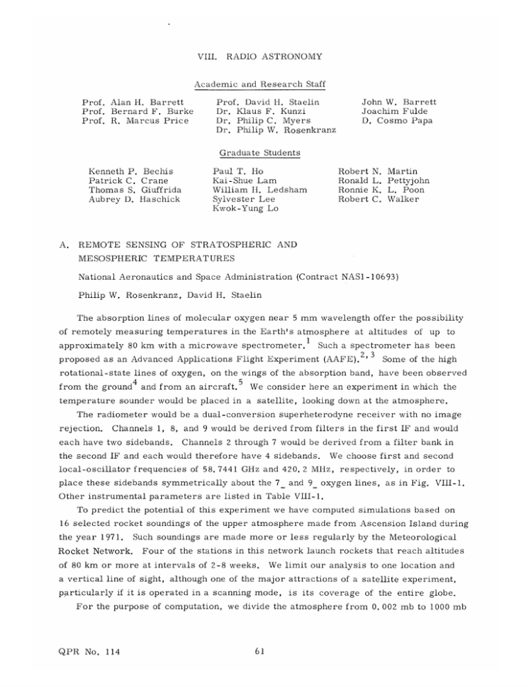
RADIO ASTRONOMY VIII. Academic and Research Staff Prof. Alan H. Barrett Prof. Bernard F. Burke Prof. R. Marcus Price Prof. David H. Staelin Dr. Klaus F. Kunzi Dr. Philip C. Myers Dr. Philip W. Rosenkranz John W. Barrett Joachim Fulde D. Cosmo Papa Graduate Students Paul T. Ho Kai-Shue Lam William H. Ledsham Sylvester Lee Kwok-Yung Lo Kenneth P. Bechis Patrick C. Crane Thomas S. Giuffrida Aubrey D. Haschick A. REMOTE SENSING OF STRATOSPHERIC Robert Ronald Ronnie Robert N. L. K. C. Martin Pettyjohn L. Poon Walker AND MESOSPHERIC TEMPERATURES National Aeronautics and Space Administration (Contract NAS1-10693) Philip W. Rosenkranz, David H. Staelin The absorption lines of molecular oxygen near 5 mm wavelength offer the possibility of remotely measuring temperatures in the Earth's atmosphere at altitudes approximately 80 km with a microwave spectrometer. from the ground 4 up to Such a spectrometer has been proposed as an Advanced Applications Flight Experiment (AAFE). 2 ' 3 rotational-state lines of oxygen, of Some of the high on the wings of the absorption band, have been observed and from an aircraft. 5 We consider here an experiment in which the temperature sounder would be placed in a satellite, looking down at the atmosphere. The radiometer would be a dual-conversion superheterodyne receiver with no image rejection. Channels 1, 8, and 9 would be derived from filters in the first IF and would each have two sidebands. Channels 2 through 7 would be derived from a filter bank in the second IF and each would therefore have 4 sidebands. We choose first and second local-oscillator frequencies of 58. 7441 GHz and 420. 2 MHz, place these sidebands symmetrically about the 7 and 9 respectively, in order to oxygen lines, as in Fig. VIII-1. Other instrumental parameters are listed in Table VIII-1. To predict the potential of this experiment we have computed simulations based on 16 selected rocket soundings of the upper atmosphere made from Ascension Island during the year 1971. Rocket Network. Such soundings are made more or less regularly by the Meteorological Four of the stations in this network launch rockets that reach altitudes of 80 km or more at intervals of 2-8 weeks. We limit our analysis to one location and a vertical line of sight, although one of the major attractions of a satellite experiment, particularly if it is operated in a scanning mode, is its coverage of the entire globe. For the purpose of computation, we divide the atmosphere from 0. 002 mb to 1000 mb QPR No. 114 260 - 250 7 7 7 7 240 230 220 8 210 9 9 9LINE 3+ LINE 7_ LINE 200 1 58.3 I 58.4 58.5 58.6 I I 58.7 58.8 58.9 59.0 59.1 59.2 FREQUENCY ( GHz) (a) 58.30 58.31 58.33 58.32 58.34 58.35 FREQUENCY (GHz) (b) Fig. VIII-I. QPR No. 114 (a) Brightness temperature spectrum from 58. 3 GHz to 59. 2 GHz as would be seen looking downward over Ascension Island, showing the positions of the instrument sidebands. Each sideband is labeled with its channel number. (b) The 9 line on an expanded frequency scale. (VIII. Table VIII-1. Channel Number Experiment parameters. The noise is calculated on the assumption of a 600 K radiometric noise temperature. The a priori brightness temperature variation is computed from rocket soundings. Passband Center Frequencies (MHz) 1 58744.1 2 58744. 1 ± 420.2 58744. 1 RMS Noise (1-s Integration) (K) RMS Variation in Observed Brightness Temperature (a priori) (K) 1.5 0.98 5.7 1.0 0.85 4.2 1.0 0.85 3.0 2. 0 0.60 3.2 2. 5 0.54 3.4 3.6 0.45 3.4 10. 0 0.27 2.9 IF Bandwidth (MHz) 420. Z2 1.2 ± 3 RADIO ASTRONOMY) 420.2 S2Z. 1 4 58744. 1 420. 2 S3. 5 58744. 75 1 420.2 S6.1 6 58744. 1 420. Z2 ± 7 58744. 1 8.7 420. Z2 ± 17. O0 8 58744. 1 176. 0 50. 0 0.17 1.5 9 58744. 1 60. 0 100. 0 0.12 1.8 into 90 layers, equally spaced along the logarithm of pressure. Each layer is therefore approximately 1 km thick. The brightness temperature (TB)i observed by channel i may be expressed as (TB) i = Z WijT j + ei, B where T. is the temperature of level j, and e. is the error of the measurement resulting from noise. Figure VIII-2a shows the weighting functions W. (j) for the nine channels, 1 computed for the magnetic latitude of Ascension Island (-15°). The populations of the states with rotational quantum numbers 7 and 9 change as functions of temperature over the range encountered in the mesosphere in such a way that the weighting functions are nearly independent of temperature, although they do depend on the magnetic Listed in Table VIII-1 are the rms variations of brightness temperature, field. averaged over the passbands of each channel, which would be seen over this location. It can be seen that the measurement noise is quite small compared with the a priori variation of the measured parameter, thereby showing that the measured brightness temperatures would provide a great deal of information about the temporal variation of the atmosphere at a given location, as well as the spatial variation over the Earth. QPR No. 114 0 0.020 0.040 0.060 0.080 0.100 0.120 WEIGHTING FUNCTION (a) 90 -2 75 -1 60 E D 0 45 0 30 15 160 180 200 220 240 260 280 300 TEMPERATURE (K) (b) Fig. VIII-2. QPR No. 114 (a) Weighting functions for Ascension Island. The received electric vector is assumed to lie in the plane of the magnetic meridian. (b) Mean temperature profile for Ascension Island. 64 (VIII. RADIO ASTRONOMY) It would be of interest, of course, to recover the temperature profile, as well as the weighted temperatures (brightness temperatures). mate of the temperature profile T 6 A minimum mean-square error esti- is given by -(TB)) + (T), = D( (2) where D = CW T- and T _i I WC W + C =_T =e (3) is the vector of estimated atmospheric temperatures, C T is the covariance matrix of atmospheric temperatures, and C =e (normally diagonal). is the covariance matrix of measurement noise Angle brackets denote the mean, and superscript t the transpose. A difficulty arises, however,. because of the small number of soundings available to compute CT. Equations 2 and 3 constitute a linear regression using 9 independent variables, but the sample size (number of soundings) is 16. Since the means are removed from the variables, the set would have only 16 - 9 - 1 = 6 degrees of freedom, which is too little to produce reliable results. We may, however, use Eq. 3 to obtain a lower bound on the errors which we could obtain by using any inversion method, since by definition it produces minimum errors for the given set of soundings. If we make the ad hoc assumption that 2 Z (CT)ijWkj = ZnrTWki , (4) where n characterizes the number of layers over which correlations persist, and a-T is an assumed a priori standard deviation of temperature, then we obtain a "minimum information" solution D== Wt t + 2 2na- e C • Typical values of 2n are 6-10 (i. e., (5) a vertical correlation length of 3-5 km) which is less than the widths of the weighting functions. The correlations between channels that are implied by Eq. 5 are therefore induced by the overlap of the weighting functions rather than by the statistics of the atmosphere. Thus we are neglecting all correlations between layers that are separated by more than the width of the weighting functions, although these correlations are known to exist. For this reason our results will be somewhat suboptimum. The columns of the matrix D (Eq. 5) may be regarded as basis functions for the QPR No. 114 Fig. VIII-3. Columns of the D matrix. RMS (K) Fig. VIII-4. QPR No. 114 RMS residuals. A - a priori. B - minimum information inversion. C - statistical inversion. (VIII. RADIO ASTRONOMY) departure of the inferred profile from the mean, when the coefficient of each function is the departure of the associated brightness temperature from its mean, as in These functions are plotted in Fig. VIII-3. Eq. 2. For these computations we used 2n T = 200 K The residual errors obtained when this inversion method is applied to the Ascension Island soundings are shown in Fig. VIII-4 by the line labeled B, along with the a priori standard deviation labeled A. is shown by the line labeled C. tics listed in Table VIII-1. The minimum mean-square error solution (statistical) The instrument errors are assumed to have the statis- We see that both solutions leave residuals of 2-3 K in the stratosphere, but 4 K or more in the mesosphere. One cause of this is certainly the greater width of the weighting functions for channels 1 and 2; atmospheric structure which is finer than the weighting functions cannot be recovered, and therefore contributes to the residuals. Possibly the soundings, which are known to possess poor reliabil- ity above 65 km, also introduce a form of noisiness in the temperature profile which is not genuine, but it is difficult to determine the extent to which this might be true. We wish to thank Dr. Joe W. Waters, of the Jet Propulsion Laboratory, California Institute of Technology, Pasadena, California, for supplying some of the computer programs used in these computations. References 1. W. B. Lenoir, J. Geophys. Res. 73, 361 (1968). 2. D. H. Staelin, J. W. Waters, and R. M. Paroskie, First Interim Yearly Report, NASA Contract NAS1-10693, July 24, 1972. 3. D. H. Staelin, J. W. Waters, and B. G. Anderson, Second Interim Yearly Report, NASA Contract NASl-10693, August 16, 1973. 4. J. W. Waters, Nature 242, 506 (1973). 5. B. G. Anderson, S. M. Thesis, Department of Electrical Engineering, M. I. T., September 1973. 6. N. E. Gaut, A. H. Barrett, and D. H. Staelin, Quarterly Progress Report No. Research Laboratory of Electronics, M. I. T. , April 15, 1967, p. 16. 7. W. L. Smith, H. M. Woolf, and W. J. Jacob, Mon. Weather Rev. 98, 582 (1970). QPR No. 114 85, (VIII. B. RADIO ASTRONOMY) MICROWAVE SPECTRUM OF THE ATMOSPHERE BETWEEN 100 GHz AND ZOO GHz U. S. Air Force - Electronic Systems Division (Contract F19628-73-C-0196) Joachim H. J. Fulde, Klaus F. Kunzi, David H. Staelin In order to determine the detectability of some atmospheric molecules, we have com- puted the microwave spectrum of the atmosphere between 100 GHz and 200 GHz at 0 and 10 km altitude. As tropospheric water vapor is one of the major absorbents, and its content is variable, we calculated the spectrum with and without H2 0 absorption. For our calculations, we used the following values. Absorption Coefficients: Oz (All calculations include Doppler broadening.) 03 J. W. Waters' programl modified for this purpose (without Zeeman splitting). 1 2-4 J. W. Waters' programl expanded to 59 lines, using L. D. Petro's program. H2 0 H 2 0 parameters from different authors compiled by Waters. CO, N 2 0 All values computed from theory after Townes and Schawlow. 5 6 Height Distributions of Molecules: HO Exponentially decreasing mass mixing ratio in the troposphere (corresponding surface density 7. 5 gm/m3), to fit the constant mixing ratio of the stratosphere (1. 5 ppm) at a breakpoint altitude of 12 km. Above 70 km water-vapor density is set to zero. 03 Distribution from U. S. Standard Atmosphere Supplements, 1966.7 N2 0 Schutz's model. 8 CO Wofsy's model. 9 Atmospheric Temperature Profile: U. S. Standard Atmosphere, 1962.10 The results of our calculations are displayed in Figs. VIII-5, VIII-6, and VIII-7. Figure VIII-5a shows the zenith spectrum (0 zenith angle), looking up from 0 km altitude; the upper curve takes into account H2 0 absorption and the lower curve does not. The two main features of the spectrum are the oxygen resonance near 118 GHz (J 1 _ transition) and the water-vapor resonance near 183 GHz; water vapor also produces a nonresonant absorption proportional to the frequency squared. Superimposed on this background are various ozone lines, which are very narrow (less than 100 MHz half-power width) because their main contribution originates from the upper stratosphere and collisions are the dominant broadening mechanism. N 2 0O and CO contributions are very weak (less than 0. 1 "K) and are not shown. Figure VIII-5b, which shows the spectrum at 10 km observing height, differs from QPR No. 114 120 140 160 FREQUENCY 180 ( GHz ) (a) 120 140 160 180 200 FREQUENCY ( GHz ) (b) Fig. VIII-5. QPR No. 114 Atmospheric spectrum at zenith between 100 GHz and 200 GHz. (a) Looking up from 0 km. (b) Looking up from 10 km. (VIII. RADIO ASTRONOMY) 300 - 200 - km O without H20 10 km 114 116 118 120 122 FREQUENCY (GHz ) Fig. VIII-6. Detailed spectrum of the 118-GHz 02 line. Fig. VIII-5a as follows: As the main contribution to H 2 0 absorption is of tropospheric origin, the two curves, well separated for 0 km, now are nearly identical (to 0.1 'K), outside the water-vapor resonance between 175 GHz and 190 GHz. The ozone lines in this part are drawn without water vapor present. With water vapor present, they have to be added to the wing of the H 2 0 absorption. Figure VIII-6 shows the 1 18-GHz oxygen line in more detail. we chose three 03 lines which are expanded in Fig. VIII-7. From Fig. VIII-5 The first three columns of VIII-7 show 03 lines. The 110. 8 GHz line was chosen because a radiometer is available for this frequency. The 142-GHz line was chosen because it is a strong line located in a window region, and the 195-GHz line is the strongest between 100 GHz and 200 GHz. The fourth column shows the NzO line at 150 GHz, which was chosen because it is located in a window. The fifth column shows the only CO line between 100 GHz and 200 GHz. This line (115 GHz) was chosen because there has recently been much interest 11 in it. , 12 The first row shows the spectra for 0 km and 0 zenith angle, with the left scale and the solid line without water-vapor absorption, and the right scale and the dashed line with water-vapor absorption. The second row shows the same spectra at 10 km. The difference with and without water-vapor absorption is of the order of a few hundredths of a degree, which cannot be shown on this scale. QPR No. 114 The third row shows these spectra when 110.836 GHz 142.17511 GHz 03 -I v0 1/0 150.7392 GHz N20 115.27119 GHz 79 35 77 100 7325 725 7690 90 67 60 151 +1 195.43053 GHz 03 03 CO 15 -I +1 V/ +1 -I +1 I 7470 -I 1/0 I V/ I +1 40 30 - 20 - z +1 -I 2o 00 J (OK) 200r 200 170 160 150 230 150 120 100 210 80 50 190 190 r F N 0 E 0 130 I: an +1 (GHz) Fig. VIII-7. -I 0 -I v/ 0 +1 -I Vo +1 -I 0 +1 Selected lines of the spectrum at various altitudes and zenith angles with and without H 2 0. Solid lines: without H 2 0. Dashed lines: with H20. (VIII. RADIO ASTRONOMY) Table VIII-2. Line amplitudes of 12 strongest 03 lines in the 100-200 GHz band, at various altitudes with and without H 2 0. we look horizontally (90 ° zenith angle) from 10 km, in order to get higher signals by increasing the path length. Except for the N20 line, there is no significant difference with and without water-vapor absorption (HZO absorption <1 "K). In Table VIII-1 we present the 12 strongest 0 3 lines between 100 GHz and Z00 GHz. The frequencies and excess brightness temperatures at 0 and 10 km are listed with and without H 20 absorption. These calculations suggest that ozone, nitrous oxide, water vapor, and oxygen can be studied because of their microwave spectra in the 100-200 GHz band, but that carbon monoxide would be very difficult to observe. References 1. J. W. Waters, "Ground-Based Microwave Spectroscopic Sensing of the Stratosphere and Mesosphere," Ph. D. Thesis, Department of Electrical Engineering, M. I. T., December 1970. 2. J. W. Waters and L. D. Petro, Quarterly Progress Report No. 96, Research Laboratory of Electronics, M. I. T., January 15, 1970, pp. 42-48. E. K. Gora, "The Rotational Spectrum of Ozone," J. Mol. Spectry. 3, 78 (1959). 3. 4. 5. M. Lichtenstein and J. J. Gallagher, "Millimeter Wave Spectrum of Ozone," J. Mol. Spectry. 40, 10 (1971). J. W. Waters, Methods of Experimental Physics, Vol. 11 (to be published). QPR No. 114 (VIII. 6. C. H. Townes and A. L. Schawlow, Company, Inc., New York, 1955). 7. U. S. Standard Atmosphere Supplements, Washington, D. C., 1967). 8. K. Schutz, 9. S. C. Wofsy, J. (1972). C. Junge, C. R. Beck, RADIO ASTRONOMY) Microwave Spectroscopy (McGraw-Hill Book 1966 (U. S. Government Printing Office, and B. Albrecht, J. McConnell, and M. B. McElroy, Geophys. J. Res. 75, Geophys. Res. 2230 (1970). 77, 4477 10. U. S. Standard Atmosphere, D.C., 1962). 11. J. H. J. Fulde and E. Schanda, "On the Detectability of Atmospheric Monoxide by Microwave Remote Sensing," Proc. Ninth International Symposium on Remote Sensing of Environment, Environmental Research Institute of Michigan in cooperation with The University of Michigan, Ann Arbor, Michigan, April 15-19, 1974. 12. V. N. Voronov, A. G. Kislyakov, E. R. Kukina, and A. I. Naumov, Akad. Nauk SSSR Fiz. Atmos. & Okeana, Vol. 8, No. 1, pp. 29-36 (1972). QPR No. 114 1962 (U. S. Government Printing Office, Washington,


