CHAPTER 33 ALTERNATING-CURRENT CIRCUITS Problem
advertisement

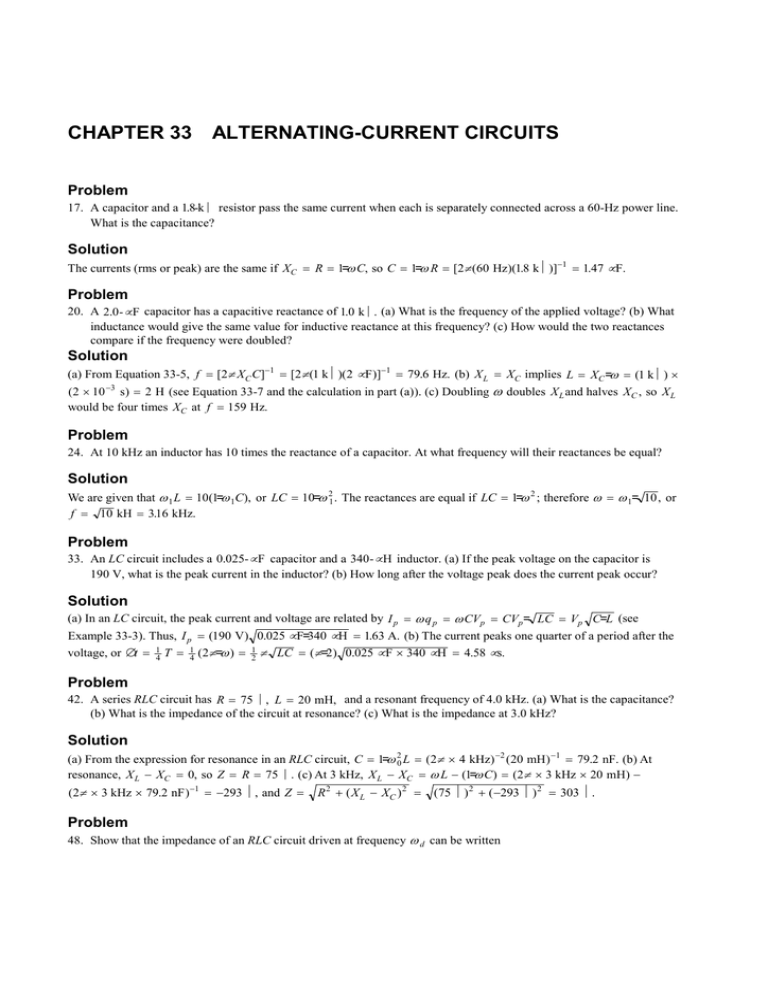
CHAPTER 33 ALTERNATING-CURRENT CIRCUITS Problem 17. A capacitor and a 1.8-kΩ resistor pass the same current when each is separately connected across a 60-Hz power line. What is the capacitance? Solution The currents (rms or peak) are the same if XC = R = 1=ω C, so C = 1=ω R = [2π (60 Hz)(1.8 kΩ)]−1 = 1.47 µ F. Problem 20. A 2.0 - µ F capacitor has a capacitive reactance of 1.0 kΩ. (a) What is the frequency of the applied voltage? (b) What inductance would give the same value for inductive reactance at this frequency? (c) How would the two reactances compare if the frequency were doubled? Solution (a) From Equation 33-5, f = [2π XC C]−1 = [2π (1 kΩ)(2 µ F )]−1 = 79.6 Hz. (b) X L = XC implies L = XC =ω = (1 kΩ) × (2 × 10 −3 s) = 2 H (see Equation 33-7 and the calculation in part (a)). (c) Doubling ω doubles X L and halves XC , so X L would be four times XC at f = 159 Hz. Problem 24. At 10 kHz an inductor has 10 times the reactance of a capacitor. At what frequency will their reactances be equal? Solution We are given that ω 1 L = 10(1=ω 1C), or LC = 10=ω 21 . The reactances are equal if LC = 1=ω 2 ; therefore ω = ω 1= 10 , or f = 10 kH = 316 . kHz. Problem 33. An LC circuit includes a 0.025- µ F capacitor and a 340- µ H inductor. (a) If the peak voltage on the capacitor is 190 V, what is the peak current in the inductor? (b) How long after the voltage peak does the current peak occur? Solution (a) In an LC circuit, the peak current and voltage are related by I p = ω q p = ω CVp = CVp= LC = Vp C=L (see Example 33-3). Thus, I p = (190 V) 0.025 µ F=340 µ H = 1.63 A. (b) The current peaks one quarter of a period after the voltage, or ∆t = 1 4 T = 1 4 (2π=ω ) = 1 2 π LC = (π=2) 0.025 µ F × 340 µ H = 4.58 µ s. Problem 42. A series RLC circuit has R = 75 Ω, L = 20 mH, and a resonant frequency of 4.0 kHz. (a) What is the capacitance? (b) What is the impedance of the circuit at resonance? (c) What is the impedance at 3.0 kHz? Solution (a) From the expression for resonance in an RLC circuit, C = 1=ω 20 L = (2π × 4 kHz) −2 (20 mH ) −1 = 79.2 nF. (b) At resonance, X L − XC = 0, so Z = R = 75 Ω. (c) At 3 kHz, X L − XC = ω L − (1=ω C ) = (2π × 3 kHz × 20 mH) − (2π × 3 kHz × 79.2 nF ) −1 = −293 Ω, and Z = R 2 + ( X L − XC ) 2 = (75 Ω) 2 + ( −293 Ω) 2 = 303 Ω. Problem 48. Show that the impedance of an RLC circuit driven at frequency ω d can be written CHAPTER 33 777 Z = R 2 + ω 2d L2 (1 − ω 20 =ω 2d ) 2 , where ω 0 is the resonant frequency. Solution Since ω 0 = 1= LC , the reactance of a series RLC circuit can be written as ωL − FG H IJ K d i 1 1 = ωL 1− 2 = ωL 1 − ω 20=ω 2 , ωC ω LC and its impedance as Z = R 2 + ω 2 L2 (1 − ω 20 =ω 2 ) 2 . (Note: In this problem, the frequency of the impressed voltage, also called the driving frequency, is denoted by ω d rather than ω.)


