Handout 4/Lab 2: Single-Cycle MIPS
advertisement
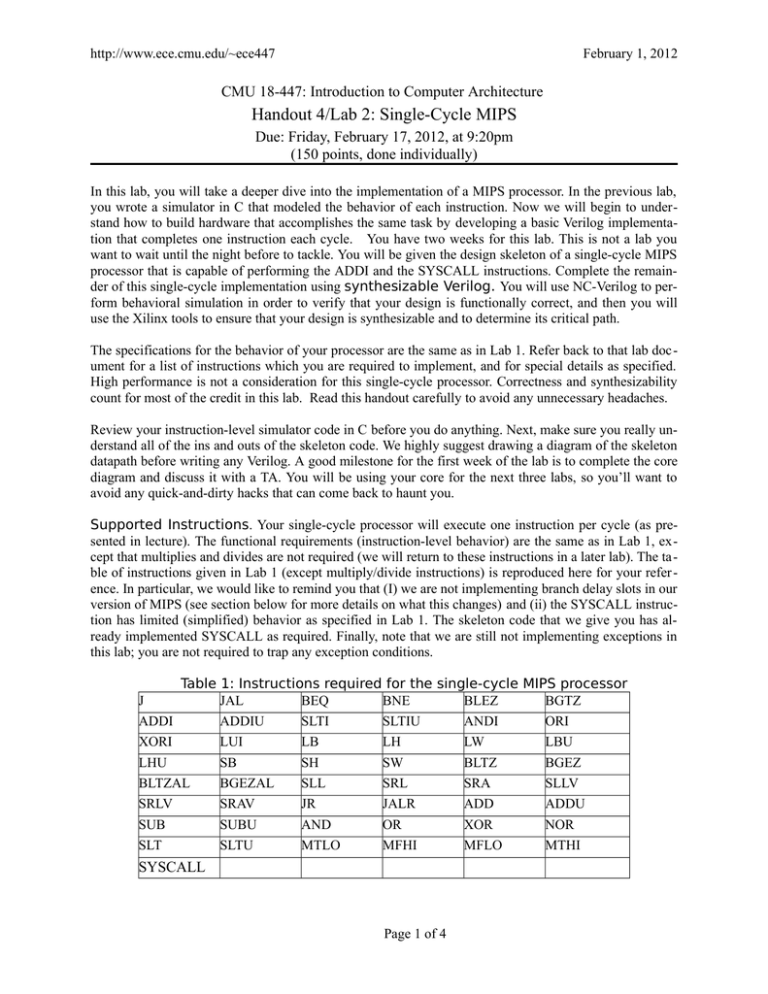
http://www.ece.cmu.edu/~ece447 February 1, 2012 CMU 18-447: Introduction to Computer Architecture Handout 4/Lab 2: Single-Cycle MIPS Due: Friday, February 17, 2012, at 9:20pm (150 points, done individually) In this lab, you will take a deeper dive into the implementation of a MIPS processor. In the previous lab, you wrote a simulator in C that modeled the behavior of each instruction. Now we will begin to understand how to build hardware that accomplishes the same task by developing a basic Verilog implementation that completes one instruction each cycle. You have two weeks for this lab. This is not a lab you want to wait until the night before to tackle. You will be given the design skeleton of a single-cycle MIPS processor that is capable of performing the ADDI and the SYSCALL instructions. Complete the remainder of this single-cycle implementation using synthesizable Verilog. You will use NC-Verilog to perform behavioral simulation in order to verify that your design is functionally correct, and then you will use the Xilinx tools to ensure that your design is synthesizable and to determine its critical path. The specifications for the behavior of your processor are the same as in Lab 1. Refer back to that lab doc ument for a list of instructions which you are required to implement, and for special details as specified. High performance is not a consideration for this single-cycle processor. Correctness and synthesizability count for most of the credit in this lab. Read this handout carefully to avoid any unnecessary headaches. Review your instruction-level simulator code in C before you do anything. Next, make sure you really understand all of the ins and outs of the skeleton code. We highly suggest drawing a diagram of the skeleton datapath before writing any Verilog. A good milestone for the first week of the lab is to complete the core diagram and discuss it with a TA. You will be using your core for the next three labs, so you’ll want to avoid any quick-and-dirty hacks that can come back to haunt you. Supported Instructions. Your single-cycle processor will execute one instruction per cycle (as presented in lecture). The functional requirements (instruction-level behavior) are the same as in Lab 1, except that multiplies and divides are not required (we will return to these instructions in a later lab). The ta ble of instructions given in Lab 1 (except multiply/divide instructions) is reproduced here for your refer ence. In particular, we would like to remind you that (I) we are not implementing branch delay slots in our version of MIPS (see section below for more details on what this changes) and (ii) the SYSCALL instruction has limited (simplified) behavior as specified in Lab 1. The skeleton code that we give you has already implemented SYSCALL as required. Finally, note that we are still not implementing exceptions in this lab; you are not required to trap any exception conditions. Table 1: Instructions required for the single-cycle MIPS processor J JAL BEQ BNE BLEZ BGTZ ADDI ADDIU SLTI SLTIU ANDI ORI XORI LUI LB LH LW LBU LHU SB SH SW BLTZ BGEZ BLTZAL BGEZAL SLL SRL SRA SLLV SRLV SRAV JR JALR ADD ADDU SUB SUBU AND OR XOR NOR SLT SLTU MTLO MFHI MFLO MTHI SYSCALL Page 1 of 4 http://www.ece.cmu.edu/~ece447 February 1, 2012 No Branch Delay Slots. For the purposes of our labs in this class, we are implementing a version of MIPS that has no branch delay slots. This is consistent with SPIM (the simulatior which you used in Homework 1) and with Lab 1. Specifically, the following branch/jump-type instructions have modified semantics relative to the MIPS manual: J PC = PC[31:28] + immediate26 << 2 JAL R[31] = PC+4; PC = PC[31:28] + immediate26 << 2 JALR R[rd] = PC+4; PC = R[rs] B<cond> if (condition) PC = PC + 4 + signext_imm16 << 2 B<cond>AL R[31] = PC+4; if (condition) PC = PC + 4 + signext_imm16 << 2 where immediate26 is the zero-extended immediate in a J-type instruction, and signext_imm16 is the sign-extended immediate in an I-type instruction. Handout Files. The files for this lab are available in /afs/ece/class/ece447/labs/lab2. The code can be built with the included Makefile; more on this later. that simulation will be placed in a new directory under runs/ that is named based on the current date and time. A summary of the supplied modules is given next. · · · · · · rtl/mips_core.v: This file contains the top-level skeleton of the MIPS processor core. The initial design is sufficiently complete that you can use the addiu.s file to test the already implemented addiu and syscall instructions as soon as you correctly plug in the register file. To complete the lab for the MIPS instructions in Table 1, you will need to make modifications including adding constants, decode logic, registers, muxes, control path and datapath. 447rtl/reg_file.v: a 3-ported register file. This is similar to your design in Lab 1.5 with the addition of an input signal named “halted”. When “halted” is asserted, a non-synthesizable behavior will print the contents of the register file to the screen and to a file “regdump.txt”. The automatic grading script will be looking for correct register file contents at the end of each run. You will need to figure out how to plug this 3-ported register file into mips447_struct.v to get started. 447rtl/sim/mips_mem_sync.v: a dual-ported multi segmented memory module. The build system will automatically assemble the .s assembly files using spim447 and plug the resulting memory image files into this module; we discuss this procedure in more detail later. rtl/mips_defines.vh: Verilog “defines” for various opcodes, instruction mnemonics, and other useful constants. This file is more complete than necessary for this lab. You only need to support the instructions in Table 1. 447rtl/sim/testjig_core.v: The file contains the top-level testjig module that combines the processor core and memory and drives them with a clock and reset signal. 447rtl/multiply_coprocessor.v: a multiply core that you will need to interface with in order to implement the MTHI, MTLO, MFHI, and MFLO instructions. Remember that we are not implementing multiplies and divides in this lab, but we will need to use this coprocessor to perform multiplies/di vides later, so we are hooking up its HI/LO data transfer paths now. To complete Lab 2, you will make modifications to the files in rtl. (If you think that you need to make modifications to a file in 447rtl, then please contact course staff!) This can include customizing the interfaces of some of the modules that have been provided; for example, you will very likely want to expand Page 1 of 4 http://www.ece.cmu.edu/~ece447 February 1, 2012 the interface that we defined for the instruction decoding logic. There are very few limitations to what you can do except: 1. The mips_core module must remain synthesizable, and must have the same portlist. 2. The register file must dump out its contents in the correct format at the end of each simulation. Test Cases. Once you plug in the register file correctly, you should be able to immediately test the design in NC-Verilog using the addiu.s test case provided. You can check the correctness by comparing the resulting regdump.txt file and the reference addiu_regdump.txt. For the demo, you will be expected to run a number of supplied programs (some revealed before the demo, some not). The available testcases are in the 447sw directory along with their expected final register file contents. In addition, you will want to build a suite of test programs to verify the operations of new capabilities in your implementation as you add them. Build System. The lab distribution contains a Makefile that implements a build system which automates many of the tedious steps in building and simulating your Verilog. To get started, run “make” to see a help message. Probably the most useful command is “make sim”, which will simulate your Verilog code with the test program defined in config.mk. When you run a simulation, the output is placed in a subdirectory of the runs/ directory which will be named with the current date and time. The build system assembles the specified test program, creates the run directory, and uses NC-Verilog to simulate your RTL with the specified test program; you will not need to worry about the details of how this is all put together. When you are ready to test whether your Verilog is synthesizable, and to see its critical path, you can use “make synth”. During the course of the lab, we may need to issue updates to the handout RTL periodically. If this is the case, you can run “make update” to pull updates from AFS space. Diagram. You will have to turn in a computer-drawn diagram of your single cycle processor for the hand-in. Your diagram should be at the same level of detail as you see in the textbook and lecture notes. All major structures (i.e., registers, muxes, incrementers, etc.) should be drawn, as well as boxes for the various control logic blocks. You should label all wires with their names and widths (this includes control path wires). For your sanity, we suggest using different colors (or line styles) to differentiate control and data path connections. We expect that you will base later diagrams off this one, so putting in an extra effort to keep this diagram neat will pay off. Don’t be afraid to leave plenty of white space and span multiple sheets of paper! Course staff recommends using Inkscape on Linux machines, or Adobe Illustrator on Windows or Mac OS machines to draw these diagrams; becoming proficient with these tools may make the diagrams much easier to draw and annotate. Handin. You should electronically hand in all of your Verilog files through the course AFS space. Hand in a paper copy of your diagram at your Lab demo period. During the demo, we will ask you questions about your single-cycle design and test it with a number of input programs. You will also need to show that your Verilog code is synthesizable by invoking the synthesis tool; you can accomplish this by running “make synth”.Please be sure to allow plenty of time to get checked off. Code submission should be done similarly to lab1. Please hand in a buildable tree into /afs/ece/class/ece447/handin/$USER/lab2 -- that is to say, there should be a file named /afs/ece/class/ece447/handin/$USER/lab2/rtl/mips_core.v, but NOT a file named .../handin/ $USER/lab2/mips_core.v, or a file named .../handin/$USER/lab2/lab1/rtl/mips_core.v. If your submission does not build when copied out of your handin directory, the automatic grading scripts will not work, and your grader will have to intervene manually, making him or her very unhappy! Page 1 of 4 http://www.ece.cmu.edu/~ece447 February 1, 2012 You should also submit a README.txt that describes details of your implementation. If you did anything ‘clever’ (hopefully!), then you should describe it. If you wrote any additional test cases, submit and describe them. Also provide a description of the critical path through your design based on the results of “make synth”. Miscellaneous Caveats. • The memory module, in file mips_mem.v provides four write enables per port. Each write enable corresponds to a byte in the memory. If you want to write a single byte in the memory, you must decode the address to enable only that byte during the write operation. • Memory accesses should be aligned to the unit of memory that you are accessing: if you are accessing bytes, any address is okay, however if you are accessing 4-byte words, only addresses where the lower two bits are zero are legal. Be aware that the multiply, divide, and mod operators in Verilog (*, /, and %) are always unsigned. If you are performing a signed operation, you need to add some code. You can still use these operators, just take care. An easy way to implement the mips_ALU module is with a behavioral case statement. The synthesis tool checks a lot more in the way of timing than the previous lab did! In particular, there are four checks that the tool performs: one for the clock, to verify that your entire design has a 25ns flop-to-flop time; one for the time to instruction address output from the clock; one for the time from instruction data return to data write available; and one for the time from data read available to the clock. This means that the tool will make a lot more noise in the timing analysis... but you still have to read it all! · Page 1 of 4
