资料版本 V1.1
归档日期 2009-06-18
BOM 编码 31012050
1.4 技术规格
UF-BCH192/10 充电器模块
1.4.1 电气参数
充电器的电气参数见表 1-2。
用户手册
表 1-2
电气参数
项目
安装使用充电器前,请仔细阅读本手册内容,以便更好地安装和使用本产品。
产品介绍
1.1 外观
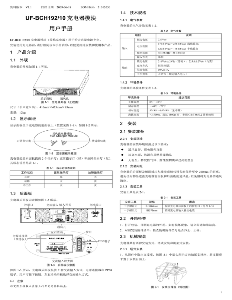
充电器的外观如图 1-1 所示。
220Vac
176±6Vac~276±6Vac 满载输出;
电压范围
输入
1
说明
额定电压
UF-BCH192/10 充电器模块(简称充电器)用于给大容量电池充电。
输出
120±6Vac~176±6Vac 半载输出
频率范围
45±0.5Hz~55±0.5Hz
输入方式
单相
额定电压
216Vdc±2Vdc(浮充),225.6±2Vdc(均充)
充电方式
恒压/恒流
限流电压
10A±1A
工作效率
≥87%(额定输入电压)
1.4.2 环境条件
充电器的环境条件见表 1-3。
10A充电器模块
10A Charger Module
常 AL
正 RM
O
N
障
故 ULT
FA
表 1-3
环境条件
环境条件
显示面板
通风孔
图 1-1 充电器外观(正视图)
尺寸(长×宽×高)
:410mm×435mm×85mm
重量:12kg
建议范围
工作温度
0℃~40℃
储存温度
-40℃~70℃
相对湿度
5%RH~95%RH(无冷凝)
海拔高度
<1500m,超过 1500m 时,参照 GB/T3859.2 降额使用
1.2 显示面板
显示面板位于充电器的前面板上(位置见图 1-1)
,如图 1-2 所示。
L
常 A
正 RM
O
N
故障指示灯
障 T
故 AUL
F
2.2.1 安装环境
充电器的安装环境应满足以下要求:
图 1-2 显示面板示意图
充电器的显示面板提供 2 个指示灯:正常指示灯(绿)和故障指示灯(红)
,
其状态说明见表 1-1。
表 1-1
安装
2.1 安装准备
10A 充电器模块
10A Charger Module
正常指示灯
2
通风良好,避免阳光直射
远离水源、热源和易燃易爆物品
无粉尘、挥发性气体、腐蚀性物质和过高的盐份
2.1.2 安装间距
指示灯状态说明
工作状态
正常指示灯
故障指示灯
充电器的后面板及侧面板应与墙壁或相邻设备间保持至少 200mm 的距离;
正常
亮
灭
避免任何物品遮盖充电器前面板和后面板的通风孔,以免阻碍充电器的通风
故障
灭
亮
散热。
不工作
灭
灭
2.1.3 安装工具
安装工具见表 2-1。
1.3 后面板
表 2-1
充电器后面板示意图如图 1-3 所示。
控制口
交流输入 输入开关
电池端口
安装工具
安装工具
规格
十字螺丝刀
EJ5100mm
拆除充电器后面板上的控制口(见图 1-3)
用途
一字螺丝刀
EJ375mm
紧固充电器输入输出电缆
2.2 开箱检查
1.打开包装,目测充电器的外观。如有损坏现象,请立即通知承运商。
通风孔
左右滑动
2.对照发货附件清单,检查随机附件型号是否齐全、正确。
按钮
电源连接器
(带滑板)
2.3 机械安装
PP30端子
充电器共有两种安装方式:塔式安装和机架式安装。
2.3.1 塔式安装
1.从附件中取出支撑座,按图 2-1 中箭头所示方向扣压支撑座,将支撑座
交流输入放大图
图 1-3 后面板示意图
平置于安装台面上。
如图 1-3 所示,充电器后面板提供 2 种交流输入方式:电源连接器和 PP30
端子。用户可按下按钮,左右滑动滑板选择交流输入方式。
注意
非艾默生授权人员禁止打开充电器机箱盖。
图 2-1 安装支撑座(俯视图)
1
连接外接电池电缆
2.将充电器放置于支撑座上。每台充电器需要安装一个支撑座,如图 2-2
2.4.2
所示。
1.断开外接电池模块的输入开关。
2.取出电池电缆,该电缆一端为 PP30 端子,一端为 3 个 OT 端子。
3.将 OT 端子相连的的红线、黑线和黄线分别与电池输入开关的正极、负
极和地线连接。如果 OT 端子与电池输入开关的接线端子不匹配,则剪去
常 AL
正 RM
NO
障 T
故 UL
FA
充电器模块
10A
10A Charger Module
OT 端子,将电池电缆剥出适当长的铜芯后,再与外接电池输入开关连接。
充电器
4.将 PP30 插头插入充电器后面板上的电池端口(位置见图 1-2)。
2.4.3 连接通讯电缆
若与 iTrust Adapt 5kVA 或 10kVA UPS 配合使用,请将 UPS 控制端口的通讯
支撑座
电缆连接到充电器后面板上的控制口。
2.5 与 UPS 的 N+1 并机系统配合使用
图 2-2 塔式安装
2.3.2 机架式安装
若与 iTrust Adapt 5kVA 或 10kVA UPS 并机配合使用,可以直接将输入电缆
1.从附件中取出挂耳和 M4×10 螺钉,通过安装孔将挂耳固定在充电器上,
连接到并机输出配电单元(POD)上的充电器端口。
如图 2-3 所示。
注意
并机系统必须由专业技术人员设置和安装。
充电器
故障处理
3
螺钉(6个)
如果充电器出现异常或故障时,请首先按表 3-1 进行检查和故障排除。如果
10A充电器模块
10A Charger Module
常 AL
正 RM
NO
问题仍然存在,请联系艾默生当地客服中心寻求技术支持或服务。
障 T
故 UL
FA
表 3-1
挂耳(2个)
安装孔(4个)
图 2-3 安装挂耳
2.将充电器放置于机架导轨上,推入充电器直到推不进为止,从附件中取
序号
故障现象
1
故障指示灯亮
2
充电器没有输出
导轨
3
机架
处理方法
充电器中有 2 个或以 充电器需维修,请联系艾默生当
上的充电板损坏
出 M6×16 螺钉,通过挂耳上的安装孔将充电器固定在机架上,如图 2-4 所
示。
故障处理表
原因分析
地客服中心获取技术支持
输入开关没有闭合
充电器机箱内发出
是否有输出
关闭充电器,切断输入电源,联
充电器内部故障
异常声响或气味
闭合输入开关,再用万用表测量
系艾默生当地客服中心
如需要向我公司或经销商反映故障情况,请务必记录并告知设备型号和编码
(充电器机箱背面条码)。
充电器
螺钉
(4个)
10A充电器模块
10A Charger Module
正常RM
NO
AL
故障UL
FA
附录一 有毒有害物质标识表
T
安装孔(4个)
图 2-4 安装充电器
有毒有害物质或元素
部件名称
2.4 电缆连接
铅
汞
镉
六价铬
多溴联苯
多溴联苯醚
Pb
Hg
Cd
Cr6+
PBB
PBDE
×
○
○
○
○
○
线缆
2.4.1 连接输入输出电缆
○:表示该有毒有害物质在该部件所有均质材料中的含量在 SJ/T-11363-2006 规定
注意事项
的限量要求以下;
1.充电器随机附带 2 根输入电缆:电源连接器输入电缆(单相三芯,250Vac,
×:表示该有毒有害物质至少在该部件的某一均质材料中的含量超出 SJ/T11363-
2006 规定的限量要求
16A)和 PP30 端子输入电缆,均可用于充电器输入,其外观分别如图 2-5
艾默生网络能源有限公司一直致力于设计和制造环保的产品,我们会通过持续的研
和图 2-6 所示。
究来减少和消除产品中的有毒有害物质。以下部件或者应用中含有有毒有害物质是
限于目前的技术水平无法实现可靠的替代或者没有成熟的解决方案:电缆头含有铅
关于环保使用期限的说明:本产品的环保使用期限(已标识在产品本体)是指在正
图 2-5 电源连接器输入电缆
常的使用条件和遵守本产品安全注意事项情况下,从生产日起本产品含有的有毒有
害物质或元素不会对环境、人身和财产造成严重影响
适用范围:UF-BCH192/10 充电器模块
图 2-6 PP30 端子输入电缆
艾默生网络能源有限公司
2.连接输出电缆时,红线连接外接电池的正极,黑线外接电池的负极,黄
地址:深圳市南山区科技工业园科发路一号
绿线接电池柜的接地端。为确保安全,首先连接地线。
邮编:518057
3.充电器的输出与电池柜之间必须接直流空开,推荐使用 600Vdc/20A 的直
公司网址:www.emersonnetworkpower.com.cn
流空开。
客户服务热线:4008876510
连接步骤
E-mail:service@emersonnetwork.com.cn
1.确认充电器外部的所有输入输出空开均处于断开位置。
资料版本
V1.1
2.将充电器的输出线与外接电池连接正确,再接到充电器的输出端。
归档日期
2009-06-18
3.根据输入端子的需求,选择电源连接器输入电缆或 PP30 端子输入电缆
BOM 编码 31012050
中的一个,将输入电缆连接到充电器上。
版权所有,保留一切权利。内容如有改动,恕不另行通知。
2
Version V1.1
Revision date June 18, 2009
BOM
31012050
UF-BCH192/10 Charger Module
Note
Non-professionals are prohibited from opening the chassis cover of the charger.
1.4 Technical Specifications
User Manual
1.4.1 Electrical parameters
The UF-BCH192/10 charger module (charger for short) is used to charge
batteries with large capacity.
The electrical parameters of the charger are listed in Table 1-2.
Table 1-2 Electrical parameters
Item
To ensure the smooth operation, please read this manual carefully before
installing and operating the charger.
1
Product Introduction
Input
Description
Rated voltage
220Vac
Voltage range
176 ± 6Vac ~ 276 ± 6Vac, full-load output;
120 ± 6Vac ~ 176 ± 6Vac, half-load output
Frequency range
45 ± 0.5Hz ~ 55 ± 0.5Hz
1.1 Appearance
Input mode
Single phase
The appearance of charger is shown in Figure 1-1.
Rated voltage
216 ± 2Vdc (float charge);
225.6 ± 2Vdc (boost charge)
Charging mode
Constant voltage/constant current
Current limiting
voltage
10A ± 1A
Operating
efficiency
≥ 87% (rated input voltage)
Output
10A充电器模块
10A Charger Module
常 AL
正 RM
O
N
障
故 ULT
FA
1.4.2 Environmental Conditions
Display panel Ventilation holes
The environmental conditions of the charger are listed in Table 1-3.
Figure 1-1 Appearance of the charger (front view)
Table 1-3 Environmental conditions
Demensions (L × W × H): 410mm × 435mm × 85mm
Environmental conditions
Recommended range
Weight: 12kg
Operating temperature
0°C ~ 40°C
1.2 Display Panel
Storage temperature
- 40°C ~ 70°C
Relative humidity
5%RH ~ 95%RH (non-condensing)
Altitude
< 1500m; derating is required when the
altitude exceeds 1500m, with reference to
GB/T3859.2
The display panel is located on the front panel of the charger (see Figure
1-1 for its position). It is shown in Figure 1-2.
10A 充电器模块
10A Charger Module
Normal
indicator
L
常 A
正 RM
O
N
Fault
indicator
障 T
故 AUL
F
2.1.1 Installation environment
The display panel of the charger provides two indicators: normal indicator
(green) and fault indicator (red). Their state descriptions are listed in Table 1-1.
Table 1-1
State description of the indicators
Normal indicator
Fault indicator
Normal
ON
OFF
Faulty
OFF
ON
Not working
OFF
OFF
The installation environment of the charger should meet the following
requirements:
Well-ventilated, avoid direct sunlight
Far away from water, heat source, flammables and explosive
substances
Free of dust, volatile gas, salt, and corrosive materials
2.1.2 Installation clearances
Maintain a clearance of at least 200mm at both sides and back of the charger.
Keep the air inlets unobstructed on the front panel and rear panel of the
charger to facilitate ventilation and heat dissipation.
1.3 Rear Panel
The rear panel of the charger is shown in Figure 1-3.
Control port
Installation
2.1 Installation Preliminaries
Figure 1-2 Display panel
Operation state
2
AC input Input switch
Battery port
2.1.3 Installation tools
The installation tools are listed in Table 2-1.
Table 2-1 Installation tools
Installation tool
Specification
Usage
Cross screwdriver
EJ5100mm
Remove the control port on the rear panel
of the charger (see Figure 1-3)
Slotted screwdriver
EJ375mm
Fix the input and output cables
Ventilation
Power linker
(with sliding
panel)
Slide
Button
PP30
terminal
2.2 Unpacking Inspection
1. Unpack the charger and visually inspect its appearance. If any shipping
damage is found, notify the carrier immediately.
2. Check against the delivery list that the types of the accessories are
complete and correct.
AC input amplified
Figure 1-3 Rear panel of the charger
As shown in Figure 1-3, the rear panel of the charger provides two AC input
modes: power linker and PP30 terminal. Users can push the button and slide
the sliding panel to choose the AC input mode.
2.3 Mechanical Installation
Two installation modes are available: tower installation and rack installation.
2.3.1 Tower Installation
1. Take out the support bases from the accessories, and snap them up in the
direction shown in Figure 2-1. Put the support bases down on the installation
surface flatwise.
1
of the battery; the yellow-green line is connected with the ground of the battery.
For the sake of safety, the output ground line must be connected first.
3. A DC MCB must be installed between the charger input and the battery
cabinet. It is recommecded to use 600Vdc/20A DC MCB.
Connection procedure
1. Confirm that all the charger input MCBs and output MCBs are open.
Figure 2-1 Installing support bases (top view)
2. Place the charger on the support bases. Each charger needs a support
base to install, as shown in Figure 2-2.
2. Connect the charger’s output cable to the battery correctly, and connect it to
the output end of the charger.
3. According to the input terminal, choose the power linker or PP30 terminal
input cable, and connect it to the charger.
2.4.2 Connecting Battery Cables
1. Switch off the input switch of the external battery module.
常 AL
正 RM
NO
障 T
故 UL
FA
充电器模块
10A
10A Charger Module
2. Take out a battery cable, one end of which is PP30 terminal and the other
end is three OT terminals.
Charger
3. Connect the red line, black line and yellow line of the OT terminal to the
positive pole, negative pole and ground line of the battery input switch
respectively. If the OT terminal is not matched with the connection terminals of
the battery input switch, cut the OT terminal and peel an appropriate length of
the copper core and then connect it to the battery input switch.
Support base
Figure 2-2 Tower installation
4. Insert the PP30 plug to the battery port (see Figure 1-2 for its position) on
the rear panel of the charger.
2.3.2 Rack Installation
2.4.3 Connecting Communiction Cables
1. Take out the brackets and M4 × 10 screws from the accessories. Use the
screws to fix the brackets onto the charger through the installation holes, as
shown in Figure 2-3.
If the charger is used together with the iTrust Adapt 5kVA UPS or iTrust Adapt
10kVA UPS, please connect the communication cable of the UPS control port
to the control port on the rear panel of the charger.
2.5 Used Together With N+1 Parallel System
Charger
If the charger is used together with the iTrust Adapt 5kVA UPS or iTrust Adapt
10kVA UPS parallel system, please lead the input cable of the charger directly
to the charger port of the parallel output power distribution unit (POD for short).
Screw (6 pcs)
10A充电器模块
10A Charger Module
常 AL
正 RM
NO
障 T
故 UL
FA
Note
Non-professionals are prohibited from installing and setting the parallel system!
Bracket (2 pcs)
Installation hole (4 pcs)
Figure 2-3 Installing brackets
2. Place the charger onto the guide rail in the rack, and push it completely into
the rack along the guide rail. Take out M6 × 16 screws from the accessories,
and use the screws to fix the charger onto the rack through the installation
holes of the brackets, as shown in Figure 2-4.
3
Troubleshooting
In the event of the charger failure, check and shoot the trouble following the
instructions provided in Table 3-1. If the failure persists, contact the local
service center of Emerson for the technical assistance.
Table 3-1 Troubleshooting table
Guide rail
No.
Rack
Fault
Possible cause
1
The fault
indicator
illuminates
2
The charger
has no output
voltage
The input switch
is not closed
Close the input switch, and use a
voltmeter to check whether the
charger has output voltage
3
Abnormal
noise or
smell in the
charger
Charger internal
fault
Turn off the charger and cut off the
power input immediately. Seek
technical assistance from the lcoal
service center of Emerson
Charger
Screw
(4 pcs)
10A充电器模块
10A Charger Module
正常RM
NO
AL
故障UL
FA
T
Installation hole (4 pcs)
Figure 2-4 Installing the charger
2.4 Connecting Cables
2.4.1 Connecting Input And Output Cables
Notes
1. The charger has two input cables in accessories: a power linker input cable
(single-phase, three-conductor, 250Vac, 16A) and a PP30 terminal input cable,
which can both be used for the charger input. Their appearances are shown in
Figure 2-5 and Figure 2-6 respectively.
Action to take
More than two
charging boards
of the charger are
broken
The charger needs repairing,
contact the local service center of
Emerson for the technical
assistance
When reporting the charger fault to Emerson or dealer, please inform charger
model and machine No. (the bar code on the rear panel of the backfeed
protection unit).
Emerson Network Power Co., Ltd.
Address: No.1 Kefa Rd., Science & Industry Park, Nanshan District 518057,
Shenzhen China
Homepage: www.emersonnetworkpower.com.cn
Figure 2-5 Power linker input cable
E-mail: support@emersonnetwork.com.cn
Copyright © 2008 by Emerson Network Power Co., Ltd.
All rights reserved. The contents in this document are subject to change
without notice.
Figure 2-6 PP30 terminal input cable
2. When connecting the output cable, the red line is connected with the
positive pole of the battery; the black line is connected with the negative pole
Version
V1.1
Revision date
June 18, 2009
BOM
31012050
2

