DESIGN, FABRICATION, AND CHARACTERIZATION OF SINGLE CRYSTAL
advertisement

DESIGN, FABRICATION, AND CHARACTERIZATION OF SINGLE CRYSTAL
SILICON LATCHING SNAP FASTENERS FOR MICRO ASSEMBLY
Rama Prasad
Sibley School of Mechanical
and Aerospace Engineering
Karl-Friedrich Böhringer
Noel C. MacDonald
Robotics & Vision Laboratory
School of Electrical Engineering &
Department of Computer Science
The National Nanofabrication Facility
Cornell University, Ithaca, NY 14853
ABSTRACT
A snap fastener is a deformable device consisting of
a pair of mating surfaces that \snap" together during
assembly. Because of the simple, linear assembly motion, such latching micro fasteners have a wide range
of applications in micro assembly tasks, e.g. for devices with multiple or layered components, or micro
opto-mechanical plugs. At the micro scale, conventional
types of fasteners like screws and hinges are unlikely to
work due to present fabrication constraints and large
friction forces. Micro snap fasteners also have great
potential to be used as sensors with memory.
We present a detailed theoretical analysis of design
and function of micro snap fasteners, and describe the
fabrication in single crystal silicon (SCS) technology.
We perform experiments on snap fasteners with 1 { 2
m wide latches. Independent comb drive actuators
generating micro-Newton forces were used for actuation of the fasteners to verify the theoretically obtained
design rules. Our experimental results are in close accordance with the theoretical predictions.
latching was observed with forces in the range of 30
N, for beams of length 50 m and width 2 m. The
total height of the beams fabricated with SCREAM was
8.5 m. The latches are 1.5 m wide, and their mating
surfaces are angled at 45. These design parameters
can be varied over a wide range to change the stiness
of the fastener.
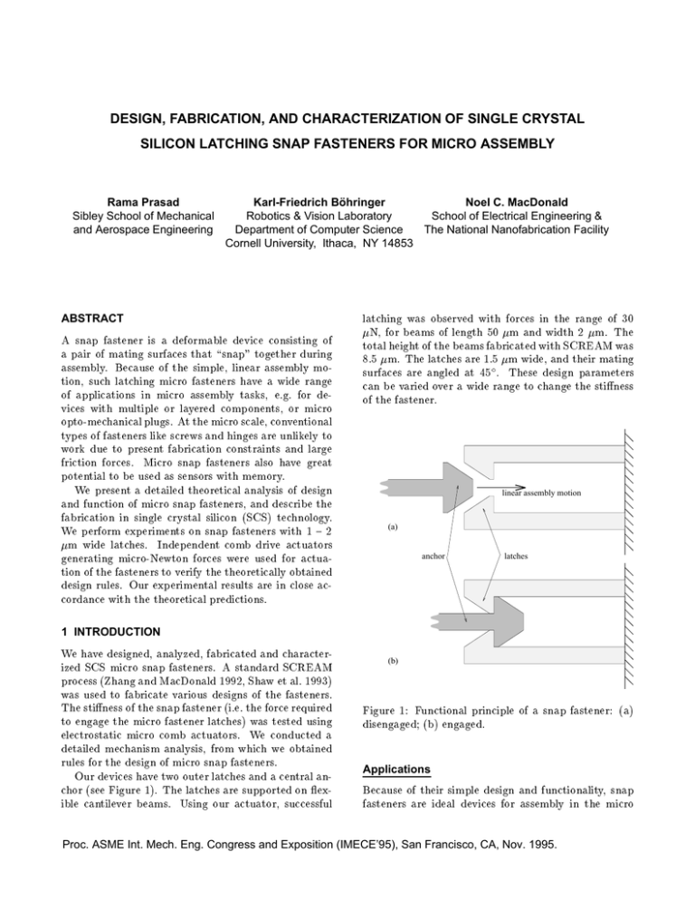
linear assembly motion
(a)
anchor
latches
1 INTRODUCTION
We have designed, analyzed, fabricated and characterized SCS micro snap fasteners. A standard SCREAM
process (Zhang and MacDonald 1992, Shaw et al. 1993)
was used to fabricate various designs of the fasteners.
The stiness of the snap fastener (i.e. the force required
to engage the micro fastener latches) was tested using
electrostatic micro comb actuators. We conducted a
detailed mechanism analysis, from which we obtained
rules for the design of micro snap fasteners.
Our devices have two outer latches and a central anchor (see Figure 1). The latches are supported on exible cantilever beams. Using our actuator, successful
(b)
Figure 1: Functional principle of a snap fastener: (a)
disengaged; (b) engaged.
Applications
Because of their simple design and functionality, snap
fasteners are ideal devices for assembly in the micro
Proc. ASME Int. Mech. Eng. Congress and Exposition (IMECE’95), San Francisco, CA, Nov. 1995.
domain. Conventional types of fasteners like screws and
nuts are less likely to work in micro assembly because
of their complicated structure and motion with high
friction. Dierent congurations of the basic latching
mechanism can be used for a wide range of applications
for micro sensors, in micro assembly and micro robotics.
Vertical micromechanical velcro has been built and
characterized by Han et al. (1992). These structures
have arrays of SiO2 caps on silicon pedestals and have
been used for wafer bonding. Pressure exceeding 12 kPa
is required to bond the velcro surfaces together. The
disengaging strength of the bond is larger than 240 kPa.
Ciarlo (1992) uses latching silicon structures as
accelerometers for moderate and high-g applications.
They consist of two cantilever beams that interlock at a
set threshold acceleration which is determined by their
design.
Polysilicon structures with integrally fabricated
hinges have been designed by Pister et al. (1992). The
hinges rotate out of plane and get xed in a vertical position by a locking mechanism which is similar
to snap fasteners. The hinges interconnect with other
structures to form 3D devices like micro-probes, parallel
plate grippers, or Fresnel lens arrays.
Micro Assembly. Complicated micro structures consisting of multiple components can be assembled together in the plane using snap fasteners. They also have
great potential when being lifted out of plane and used
as vertical plug-in connectors. Multi-layered structures
can be built using these plugs. Currently under investigation is another application for micro opto-mechanical
plugs, in which optical bers are accurately attached.
The connectors can be used both for electrical or insulated connections.
These fasteners have tremendous applications as sensors. Varying congurations in combination with supporting electronic circuitry can be used to sense pressure, temperature, acceleration, impact etc. They can be designed to measure either force or displacement. Their hysteretic behaviour allows them to be used as sensors with memory.
Arrays of these devices with increasing stiness can be
used to determine the magnitude of the engaging force.
tion 5 summarizes our work and gives an outlook on
future work and open questions.
2 DESIGN AND MECHANICAL ANALYSIS
A snap fastener consists of a mating pair of an anchor
and exible latches (see Figure 1). In its disengaged
state anchor and latches can move freely with respect to
each other. To engage the device, the anchor is moved
along a straight line towards the latches as depicted
in Figure 1(a), such that the anchor comes in sliding
contact with the latches, causing them to bend outward,
until the anchor is fully inside the latches. The following
properties of snap fasteners are of particular interest:
1. Assembly is simpler than e.g. with screws or nuts,
as only a linear motion is required to engage the
components.
2. Assembly is robust, i.e. small errors in the relative
position of anchor and latches are corrected automatically by their chamfered surfaces.
3. The force required to engage the fastener can be
chosen over a wide range depending on the shape
and size of the device.
4. The force to engage can be made much smaller
than the force to disengage (motion diode).
5. The device has two stable states, disengaged and
engaged, with hysteresis characteristics depending
on the device design.
Snap fastener design and analysis follow the discussion
by Donald and Pai (1991), where a more detailed theoretical analysis can be found.
l
σ
θ
w
∆
Sensors with Memory.
Figure 2: Design schematic of a snap fastener.
Overview
Mechanism Design
In the following section we give a detailed description of
snap fastener design and mechanism analysis. We identify the design parameters and describe their eect in
terms of design rules. Section 3 contains the fabrication
process and its eect on the mechanism design. In Section 4 we present the results from our experiments and
compare them with our theoretical predictions. Sec-
Consider the schematic drawing of a snap fastener in
Figure 2. Each latch consists of a exible cantilever
beam of length l, width w, and (not shown) height h.
At the tip of the beam there is a latching mechanism
whose shape matches with the anchor. The anchor has
chamfered sides, such that the front chamfer is sloped
at an angle , and the back chamfer is sloped at an angle
Proc. ASME Int. Mech. Eng. Congress and Exposition (IMECE’95), San Francisco, CA, Nov. 1995.
.
The width of overlap between latch and anchor is
called .
fn
f
and (tangential) friction force fr = ft are related by
ft = fn . It follows that the angle in Figure 3(b) is
independent of the applied force f , and tan = ft =fn =
. Therefore, the sum fn + ft is in general not equal
to the applied force f . The dierence is a perpendicular force fp which has to be provided by the anchor
structure. This perpendicular force will push the latch
outward until it engages.
ft
θ
(a)
spring
φ
fn
∆
fp
θ
f
ft
(b)
θ
Figure 3: Forces during snap fastener assembly: (a)
sticking contact (higher coecient of friction), (b) sliding contact (lower coecient of friction).
Mechanism Analysis
In the following we analyze the design in greater detail. Assume we want to engage the snap fastener by
applying a force f in the direction of assembly. Once
anchor and latch are in contact, there are two possibilities: anchor and latch are in sticking frictional contact (Figure 3(a)), or in sliding frictional contact (Figure 3(b)). For sticking contact, f will cause a normal
force fn = f sin acting on the latch. The tangential
component ft = f cos will be balanced out by the
friction force fr .
Previous work by Prasad et al. (1995) has shown
that we can assume Coulomb friction, where the friction force fr is proportional to the normal force fn and
the friction coecient , such that fr = fn . Under
Coulomb friction sticking occurs when the tangential
force ft is less than the friction force fr . To avoid sticking we must therefore make sure that the following condition holds:
ft
>
fr
so
f cos > f sin which implies
cot > (1)
A similar analysis applies for disassembly, where will
be replaced by .
If the device is in sliding frictional contact,
Coulomb's friction law predicts that normal force fn
Figure 4: Linear spring model for snap fastener.
For the small angles of deection occuring during assembly we can model the latches as linear springs obeying the relationship f = K, with spring constant K ,
deection , and corresponding retracting force f (see
Figure 4). The spring constant can be determined from
the latch geometry by K = 3EI
l3 , where E is the Young's
3
hw
Modulus, and I = 12 (for derivation of formulas see
e.g. Juvinall and Marshek (1983)).
To overcome the spring force f we get the following
condition:
fp > f
for all so
f cot( + ) > f
which implies
f > K tan( + )
= K 1,+tan
tan (2)
Equations (1) and (2) specify the design rules for snap
fasteners. They state that cot has to be greater than
the friction coecient . They further predict that the
force necessary to engage a snap fastener is proportional
to the spring constant K = 3EI
l3 , the latch overlap ,
and the tangent of + .
Design Parameters
We dene stiness of a snap fastener as the force required to engage a particular fastener conguration.
The design parameters aecting the stiness of the fasteners are the length l, width w and height h of the
supporting beams (Figure 2). The latch overlap and
the angle also eect the stiness according to equation (2). The width w and height h are constrained by
Proc. ASME Int. Mech. Eng. Congress and Exposition (IMECE’95), San Francisco, CA, Nov. 1995.
Figure 6: Micro snap fastener (detail).
Figure 5: Micro snap fastener (SEM micrograph).
the SCREAM process. To ensure release using standard SCREAM the nal beams cannot be wider than
2 m, and for straight side walls obtainable from Cl2
RIE we have restricted the height to at most 10 m.
The width of the latches has been chosen to be 1 m
such that the total width of the beam and the latches
is not larger than 2 m for release. The angle has
been selected to be 45. The coecient of friction for
SCREAM fabricated surfaces has been determined by
Prasad et al. (1995) to range from 0.3 to 0.5. Figures 5 {
7 show SEM pictures of such devices.
We have chosen the length l of the beams and the
chamfer angle to be the design parameters of major
interest, as they can be varied over a wide range of values, and they have the maximum eect on the stiness.
We have built fasteners with lengths ranging from 20
m to 50 m. However, very long cantilevered beams
(> 100 m) may sag and bend out of plane due to residual stresses arising from processing.
Actuator Device
To test the stiness of the snap fasteners, we have
mounted them on lateral comb drive actuators. These
actuators have been well characterized by Prasad et al.
(1995). Two actuators exert the engaging force from
both sides of the fastener (Figure 8). Each actuator
has N = 350 ngers on ladder beams. The nal gap
between ngers after fabrication is d = 1:5 m, and the
height of the ngers is h = 8:5 m. The force generated
by these actuators is given (Prasad et al. 1995) by the
formula
1
2
(3)
f =
2 hN V =d
Figure 7: Micro snap fastener (side view).
which for our values is f = 1:32 10,8 (V 2 ) N, for a
voltage V in volts. We can apply up to 80 V across
the ngers without break down of the passivating oxide
layer. This generates forces up to 80 N, which is well
within the range of the force required to engage the
snap fasteners for the beam lengths we have studied.
Design Automation
There exist ecient computational tools for analysis and simulation of snap fasteners. Donald and
Pai (1991) have presented an ecient algorithm to automatically analyze snap fasteners with arbitrary designs,
and predict their behavior during compliant frictional
contact. Using their techniques it is possible to automatically generate the appropriate design of a snap
Proc. ASME Int. Mech. Eng. Congress and Exposition (IMECE’95), San Francisco, CA, Nov. 1995.
Figure 8: Micro comb drive actuator (SEM micrograph).
fastener given just the functional specication of the device. An outline for such an automatic design algorithm
has been presented by Bohringer (1993). Combined
with the highly automated VLSI fabrication process,
this allows a virtually completely automated production, making snap fasteners one of the very few devices
that can be fabricated automatically given only their
functional specication.
3 DEVICE FABRICATION
We have used standard SCREAM to fabricate our
device. The layout of the complete device comprising of the fastener latches and the two actuators was
drawn using SYMBAD, a CAD package for IC circuits. SCREAM (Zhang and MacDonald 1992, Shaw
et al. 1993) is a single mask, reactive ion etching process for the fabrication of submicron, movable singlecrystal silicon electromechanical structures. We followed a variation of SCREAM for releasing 2 m wide
beams.
The process ow for releasing a beam in cross section
is shown in Figure 9. PECVD is used to deposit insulating layers of SiO2 . Chlorine based reactive ion etching is used for trench etching into the silicon substrate.
On the starting substrate of arsenic-doped, 0.005 cm,
n-type (100) silicon wafer, a 2.4 m thick etch mask
layer of silicon dioxide was deposited using plasma enhanced chemical vapor deposition at 300 C, 450 mT,
N2O ow of 42 sccm and SiH4 ow of 12 sccm for 60
min. Photolithography is used to transfer the pattern
from the mask onto a layer of KTI 985i 16.5cs positive
Figure 9: SCREAM process ow.
Proc. ASME Int. Mech. Eng. Congress and Exposition (IMECE’95), San Francisco, CA, Nov. 1995.
resist spun on the oxide. The minimum feature size in
our device is 1 m thick beams of our fastener. The
pattern is transferred from the resist layer to the oxide
layer using MRC Magnetron ion etching at 2 mT at a
ow rate of 30 sccm of CHF3 at 1000 W. The photo
resist is removed using O2 plasma etch.
The pattern is transferred into the silicon substrate
from the silicon oxide layer using Cl2 reactive ion etching in a Plasma Therm PK-1250 at 30 mT, 450 V and at
a ow rate of 50 sccm for Cl2 and 1.5 sccm BCl3 for 45
min to get 8 m deep trenches. This trench depth determines the beam heights. We used lower pressure and
higher voltage for nearly vertical sidewalls. The sidewall slopes determine contact area when the fastener
is latching. Vertical side walls are desirable as ared
side walls will lead to line contact at the bottom of the
latches leading to unpredictable behavior. Following
this an insulating layer of silicon dioxide is deposited
for side wall passivation using PECVD at the parameter values stated above for 15 min giving a 400 nm thick
oxide layer. CHF3 reactive ion etching is again used to
remove the oor oxide for subsequent substrate etches.
A short Cl2 reactive ion etch at 50 sccm Cl2 and 5
sccm BCl3 , 40 mT and 400 V for 20 min generates 5
m deep trenches in the substrate to aid in the following release etch of 2 m wide beams. All the beams
of thickness up to 2 m are released from the silicon
substrate using SF6 RIE process in a Plasma Therm
72 RIE system. A SF6 plasma with a SF6 ow rate
of 140 sccm at 90 mT and 150 W was used to release
the beams in 6 min. A 100 nm thin layer of silicon
oxide was deposited to avoid any shorting between the
conducting Al layer and the silicon substrate. A 500
nm layer of Al is conformally deposited using DC magnetron sputtering performed at 30 mT pressure, with a
beam current of 5 A and argon ow rate of 30 sccm.
A 100 nm thick layer of oxide is nally deposited
on the device to avoid shorting when the latches make
contact during operation. The structural beams nally
are 8.5 m tall, including the deposited layers. The
cantilever beams comprising the latches are 50 m long,
8.5 m tall and are nally 2.0 m thick.
Design Modifications
For our initial design we had used latch dimensions of
= 50 m, w = 1 m, = 1:5 m, and = 45 (Figure 2). The gap between the two outer latches was 10
m. This gap was too small, so that the PECVD oxide
did not coat the inner and outer side walls uniformly,
leading to residual stressed which bend the beams outward. To ensure uniform lms on both inner and outer
walls we changed the fastener design to more widely
spaced beams ranging from 20 m to 40 m. Another
variation was to put two beams on the outside of the inner beams, leading to both side walls of the latch beams
Figure 10: Engaged micro snap fastener (SEM micrograph).
being 10 m away from other beam sidewalls (Figures 5
and 10). Both variations produce straight cantilevered
beams for supporting the latches using the standard
SCREAM process outlined above.
4 EXPERIMENTAL RESULTS AND PERFORMANCE
Predictions from Design Analysis
We now use the theoretical results from Section 2 to
predict the behavior of our micro snap fasteners. From
Equation (2) we know that the force f required to engage a snap fastener is
3(EI )e tan( + )
f = K tan( + ) =
l3
The SCREAM fabrication process gives us beams
coated with lms of SiO2 of 0.5 m thickness. The
silicon core is 1 m wide and 8 m high. Hence, the
eective spring constant Ke is composed of KSi of the
Si beam core, and KSiO2 of the coating.
KSi
l
KSiO2
8 m (1 m)3
= 190 GPa
4 (50 m)3
= 3:04 N/m
= [73 GPa (8 m ((2 m)3 , (1 m)3)
+ 0:5 m (2 m)3)] = (4 (50 m)3 )
= 8:76 N/m
= KSi + KSiO2 = 11:8 N/m (KAl for the thin
Al layer is neglectable). E is the Young's Modulus.
Figure 11 shows the relationship between beam length
Ke
Proc. ASME Int. Mech. Eng. Congress and Exposition (IMECE’95), San Francisco, CA, Nov. 1995.
Snap fasteners have a wide range of applications, especially for various sensors with memory, for the assembly of complex micro devices, for micro opto-mechanical
structures, and in micro robotics.
−4
2.5
x 10
2
force f [N]
ACKNOWLEDGEMENTS
1.5
1
0.5
0
2
2.5
3
3.5
4
4.5
5
beam length l [m]
5.5
6
−5
x 10
Figure 11: Relationship between chamfer beam length l
and assembly force f for chamfer angles (top to bottom)
= 60 , 45 , and 30 .
and required force f for three dierent chamfer angles.
was 1.5 m, and = 0:3.
This work was supported by ARPA under contract DABT
63-69-C-0019. The device fabrication was performed at
the National Nanofabrication Facility (NNF), which is supported by the NSF grant ECS-8619049, Cornell University,
and Industrial Aliates. Support for the second author was
provided in part by the National Science Foundation under
grants No. IRI-8802390, IRI-9000532, IRI-9201699, and by
a Presidential Young Investigator award to Bruce Donald,
in part by NSF/ARPA Special Grant for Experimental Research No. IRI-9403903, and in part by the Air Force Oce
of Sponsored Research, the Mathematical Sciences Institute,
Intel Corporation, and AT&T Bell laboratories.
The authors would like to thank Bruce Donald for useful
discussions and valuable comments. The idea of using his
snap fastener designs (Donald and Pai 1991) in MEMS devices also originated from Bruce Donald. We thank users,
sta and students at the National Nanofabrication Facility
at Cornell University for their technical assistance.
l
Experimental Results
We observed engagement of our snap fasteners with the
design as described above at voltages between 50 and 70
V. According to Equation (3) in Section 2 this implies
forces in a range between 22 and 43 N. This range is
drawn in Figure 11 as vertical bar. We observe that
theoretical predictions match with the experimental results.
5 CONCLUSIONS AND FUTURE WORK
We have described a SCS micro snap fastener. From
the mechanism analysis presented, we can vary the stiness of such fasteners, using the design rules developed
above as guidelines. SCREAM was used to fabricate
the device consisting of the fasteners and the actuators
generating the force required for engagement. Some
design modications were incorporated to get closely
spaced parallel beams 1 m wide and 50 m long using SCREAM. The fasteners were successfully engaged
using the actuators at the predicted voltage of 50 V,
generating 30 N, which veries our analysis.
The design rules can be used to construct dierent
variations of these fasteners. Other congurations allowing us capabilities like controlled disengagement can
also be similarly built using the latches and actuators
with SCREAM. We also propose to investigate the effect of the various design parameters, as well as study
of wear on repeated snap operations.
REFERENCES
Bohringer, Karl-Friedrich 1993. A computational approach
to the design of micromechanical hinged structures. In
Proceedings of the ACM/SIGGRAPH Symposium on Solid
Modeling and Applications, Montreal, Quebec, Canada.
ACM Press.
Ciarlo, Dino R. 1992. A latching accelerometer fabricated
by the anisotropic etching of (110) oriented silicon wafers.
Journal of Micromechanics and Microengineering 2.
Donald, Bruce R. and Pai, Dinesh K. 1991. The motion of
compliantly connected rigid bodies in contact. Int. Journal
of Robotics Research.
Han; Weiss; and Reed 1992. Micromechanical velcro. Journal of Microelectromechanical Systems.
Juvinall, Robert C. and Marshek, Kurt M. 1983. Fundamentals of Machine Component Design. Wiley, New York.
Pister, K.S.J.; Judy, M.W.; Burgett, S.R.; and Fearing,
R.S. 1992. Microfabricated hinges. SAA 33(3):249{256.
Prasad, Rama; MacDonald, Noel C.; and Taylor, Dean
1995. Micro-instrumentation for tribological measurements. In Transducers | Digest Int. Conf. on Solid-State
Sensors and Actuators, Stockholm, Sweden.
Shaw, Kevin A.; Zhang, Z. Lisa; and MacDonald, Noel C.
1993. SCREAM I: A single mask, single-crystal silicon process for microelectromechanical structures. In Transducers
| Digest Int. Conf. on Solid-State Sensors and Actuators,
Pacico, Yokohama, Japan.
Zhang, Z. Lisa and MacDonald, Noel C. 1992. An RIE
process for submicron, silicon electromechanicalstructures.
Journal of Micromechanics and Microengineering 2(1):31{
38.
Proc. ASME Int. Mech. Eng. Congress and Exposition (IMECE’95), San Francisco, CA, Nov. 1995.


