BODY OF TOY DUCK 20 mm THICK MDF
advertisement
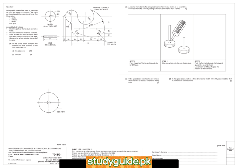
Question 1 (i) the side view; (ii) the plan. Ø8 60 R10 R10 40 0 16 R 24 WHEEL 20 mm THICK MDF 40 R (a) In the space below complete the following full size drawings of the fully assembled toy: Ø50 40 R Assembly instructions 1 Paint the parts of the toy duck and allow to dry. 2 Glue one wheel onto the end of each axle. 3 Insert an axle into each of the Ø9 holes and push through the body of the duck. Glue another wheel onto the free end of the axle. (b) A pictorial instruction leaflet is required to show how the toy duck is to be assembled. Complete the leaflet below by adding suitable illustrations for steps 1 and 3. [5] 30 R Orthographic views of the parts of a wooden toy duck are shown on the right. The toy is purchased as a kit for assembly at home. The kit contains: 1 × body; 4 × wheels; 2 × axles; PVA glue. BODY OF TOY DUCK 20 mm THICK MDF 64 10 AXLE Ø8 mm DOWEL 30 30 30 70 160 30 2 HOLES Ø9 FOR AXLES [13] [8] STEP 1 Paint the parts of the toy and leave to dry for 24 hours. (c) In the space below use sketches and notes to show one idea for a colour scheme for the toy duck. [2] STEP 2 Glue one wheel onto the end of each axle. STEP 3 Push the front axle through the body and glue on the second wheel. Leave to dry for 1 hour. Repeat the process for the back axle. (d) In the space below produce a three dimensional sketch of the fully assembled toy duck in your chosen colour scheme. [6] SIDE VIEW PLAN VIEW UNIVERSITY OF CAMBRIDGE INTERNATIONAL EXAMINATIONS Joint Examination for the School Certificate and General Certificate of Education Ordinary Level CDT: DESIGN AND COMMUNICATION 7048/01 Paper 1 October/November 2006 No Additional Materials are required 2 hours 30 minutes plus 15 minutes reading time © UCLES 2006 IB06 11_7048_01/5RP [Turn over SHEET 1 OF 2 (SECTION 1) Print your surname, other names, Centre number and candidate number in the spaces provided. Answer one question only from Section 1 (Questions 1 and 2). Answer two questions only from Section 2 (Questions 3 to 6). Answer the questions in the spaces provided. All construction and projection lines must be clearly shown in Section 2. All dimensions are in millimetres unless otherwise stated. The number of marks is given in brackets [ ] at the end of each question or part question. http://www.xtremepapers.net For Examiner’s use Candidate’s Surname .................................................................................................................. Other Names ............................................................................................................................... Centre Number ............................................................................................................................ Candidate’s Number .................................................................................................................... (d) Design 1 for the en suite bathroom and Design 1 for the study bedroom have been selected as the final layout. Draw a planometric view of this final design proposal to a scale of 1:25. Corner A has been given as a starting point. The walls are 2400 mm high. Estimate any dimensions not given. [14] Question 2 3900 A sketch of a study bedroom in a boarding school is shown on the right. 200 SHOWER TRAY WASH BASIN 500 2900 500 390 390 1100 WINDOWS ENTRY DOOR TO BEDROOM SOMEWHERE ALONG THIS WALL 600 500 500 800 800 200 The teachers are to consider the possibility of having an en suite bathroom facility in the single rooms provided for senior students. The specification points for the en suite bathroom facility are: • size of en suite bathroom 1900 mm × 1800 mm; • access to en suite bathroom via a 750 mm wide internal door from the study bedroom; • internal walls separating the en suite bathroom and the study bedroom are to be 100 mm thick; • the en suite bathroom to include a shower, washbasin and a toilet. The sizes of these are shown below. 600 STUDY BEDROOM SCALE 1 : 50 CORNER A TOILET (a) A sketch of a possible layout for the en suite bathroom is shown below as Design 1. In the spaces provided use sketches and notes to show two further ideas for the position of the en suite in the study bedroom and the layout of the facilities (shower, washbasin and toilet). [6] WASH BASIN SHOWER TOILET DESIGN 2 900 The study bedrooms are to be equipped with: • a bed 1900 mm long × 900 mm wide; • a table in plan 1000 mm × 475 mm; • a bookcase in plan 600 mm × 300 mm; • a wardrobe 900 mm wide by 600 mm deep in plan. DESIGN 3 600 900 1900 BED EN SUITE 1000 300 600 DESIGN 1 475 CORNER A TABLE BOOKCASE WARDROBE BED WARDROBE TABLE BOOKCASE CORNER A DESIGN 1 DESIGN 2 DESIGN 3 (b) A sketch of a possible layout for the study bedroom is shown above as Design 1. In the spaces provided use sketches and notes to show two further ideas for the layout of the furniture in the study bedroom. Show the position of the en suite bathroom in the study bedroom but do not include details of the shower, washbasin and toilet. [6] 45° 45° CORNER A (c) Combine the best of your designs for the en suite bathroom and the study bedroom to produce a 1:50 scale plan view of this final design proposal in the space to the right. [5] (e) To the above drawing add a colour scheme based upon the theme ‘peace and harmony’. YOUR FINAL DESIGN SCALE 1 : 50 © UCLES 2006 [3] Ø4 LOCATING PEGS Question 3 Question 4 A small area of a park is to be turned into a children’s play area. The designer wishes to produce a 1:200 (5 mm = 1 metre) illustration of the play area so that local residents can consider the proposal. A sketch of a puzzle is shown on the right. The puzzle is made from 4 layers of 10 mm thick acrylic that stack on a base. The layers are located in position on the 10 mm thick base by pegs. Each of the layers has a geometric shape cut out of the centre. (a) In the space below complete the outline of the play area from the following information. AB = 24 metres DE = 22 metres BD = 30 metres BC = 20 metres EA = 14 metres (a) Complete the full size drawing of each of the layers by adding the missing geometric shape. Each shape is in the centre of the layer. Layer 3 has been completed for you. [9] CD = 16 metres Angle ABC = 90° [8] A A LAYER 4 LAYER 3 LAYER 2 LAYER 1 BASE Layer 4 - 20 mm square Layer 3 - Equilateral triangle length of side 20 mm (b) In the space below complete a full size sectional drawing of the assembled puzzle. The section is to be taken through the cutting plane A-A as indicated on the sketch above. [12] A Layer 2 - Octagon circumscribing a 25 mm diameter circle Layer 1 - Hexagon length of side 12 mm (c) Produce an exploded pictorial sketch of the puzzle showing the base, location pegs and layer 4. Do not show layers 1, 2 or 3. [12] B (b) Trees with a spread (diameter of branches) of 6 metres are to be planted at each corner of the play area. An example of a tree is given at corner A. Add the four missing trees to your illustration of the play area. [6] (c) A path, two benches and sand pit are to be included in the play area. In the box on the right produce a sketch and notes to show your idea for the layout of these features in the play area. Consider the following specification points in your designs. • The path is 1 metre wide and starts at the middle of side AB and gently curves across to the middle of side DE in a radius of 22 metres. • A sand pit with an area of 64 m2 is to be positioned so that it is not under the spread of any of the trees. • Two benches (each 2.5 metres long and 0.5 metres wide) are to be positioned close to the path so that parents can watch their children play in the sand pit. [7] BASE SECTION ON A-A (d) Add the path and your chosen layout for the benches and sand pit to the 1:200 illustration of the play area. [6] (e) Add appropriate colour and labels to complete the 1:200 illustration of the play area. [6] Idea for the layout of the play area [Turn over UNIVERSITY OF CAMBRIDGE INTERNATIONAL EXAMINATIONS Joint Examination for the School Certificate and General Certificate of Education Ordinary Level CDT: DESIGN AND COMMUNICATION 7048/01 Paper 1 October/November 2006 No Additional Materials are required 2 hours 30 minutes plus 15 minutes reading time © UCLES 2006 IB06 11_7048_01/5RP SHEET 2 OF 2 (SECTION 2) Print your surname, other names, Centre number and candidate number in the spaces provided. Answer one question only from Section 1 (Questions 1 and 2). Answer two questions only from Section 2 (Questions 3 to 6). Answer the questions in the spaces provided. All construction and projection lines must be clearly shown in Section 2. All dimensions are in millimetres unless otherwise stated. The number of marks is given in brackets [ ] at the end of each question or part question. For Examiner’s use Candidate’s Surname .................................................................................................................. Other Names ............................................................................................................................... Centre Number ............................................................................................................................ Candidate’s Number .................................................................................................................... Question 5 Question 6 A flower growing business called A, P & N has produced the table below to show the quarterly sales figures for two types of flower that were supplied to a supermarket during the last year. A drawing of a toy rocket and package are shown below. The main sizes are given. Use your judgement to determine any sizes not given. 7000 10 050 2nd quarter Apr - Jun 5750 9400 3rd quarter July - Sept 3250 6200 4th quarter Oct - Dec 9550 6900 Total 25 550 32 550 (b) A logo on the toy rocket is to be visible through a window in the box. Draw on your development (net) the window in a suitable size and position. [4] GLUE TAB CONICAL NOSECONE (a) The flower growing business wishes to show these figures in the form of a bar chart on the given axes to the right. The bar chart must: POSITION OF CARD INSERT A BAR CHART 100 LOGO 70 (i) show the quarters of the year horizontally and the number of flowers sold vertically; (ii) use red and yellow to show the two type of flower; POSITION OF CARD INSERT B (iii) have the quantity added to each bar. [8] 40 During the same year a pack of mixed coloured flowers was also supplied to the supermarket. Sales of this product totalled 13 900 in the year. 40 Complete the bar chart on the given axes on the right. GLUE TAB 1st quarter Jan - Mar 30 Yellow QUANTITY Red (a) In the space provided complete the full size drawing of the one piece development (net) of the packaging for the rocket. Clearly show all fold lines, glue tabs and fold-in flaps. [16] (b) On the centre lines provided draw a pie chart to illustrate the quantity of the three types of flower supplied to the supermarket during the year. Colour code your chart and use appropriate labels. [7] PIE CHART CARD INSERT HEIGHT OF RIDGE HEIGHT OF EAVE 1 /2 AB 50 mm (c) Complete the one point perspective drawing of the glasshouse block. The two spans are to be drawn on the given horizontal line AB. The vanishing point (VP) is also given. [7] 32 30 mm To produce flowers throughout the year they have to be grown in glasshouses. Each block of glasshouses has 2 spans. The height of the eaves and ridge of each span is given in the small sketch on the right. A drawing of a glasshouse block is to be used as part of a company logo. Ø18 (c) The package includes two card inserts that prevent the rocket from moving in the box. These are positioned at levels A and B. Complete the drawings [9] of the card inserts in the space below. (d) The package for the toy rocket is to be hung on a display rack in shops. A drawing of part of the display rack is shown below. Use sketches and notes to show how the original net could be modified to allow it to be hung on the display rack. [4] NOT TO SCALE V.P. CARD INSERT A A (d) In the box on the right use a sketch and notes to show how the company could use their initials A, P & N in the logo. Add your chosen logo to the one point perspective drawing above. Apply appropriate colour to your logo. [10] © UCLES 2006 DISPLAY RACK B Idea for the logo CARD INSERT B Permission to reproduce items where third-party owned material protected by copyright is included has been sought and cleared where possible. Every reasonable effort has been made by the publisher (UCLES) to trace copyright holders, but if any items requiring clearance have unwittingly been included, the publisher will be pleased to make amends at the earliest possible opportunity. University of Cambridge International Examinations is part of the University of Cambridge Local Examinations Syndicate (UCLES), which is itself a department of the University of Cambridge.

