Dayside tutorial: Jim Burch GEM Workshop, Portsmouth, VA June 17, 2014
advertisement
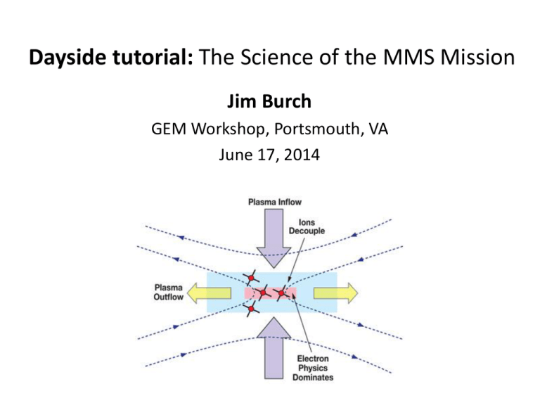
Dayside tutorial: The Science of the MMS Mission Jim Burch GEM Workshop, Portsmouth, VA June 17, 2014 Outline •Fundamental Aspects of Magnetic Reconnection •The Magnetospheric Laboratory •Scale Sizes and Measurement Requirements •Magnetospheric Multiscale Mission •Orbital Strategy and Burst-Mode Data •Summary June 17, 2014 Jim Burch 2 What is Magnetic Reconnection? • Magnetic fields pointing in opposite directions in converging plasmas tend to annihilate each other in a diffusion region, releasing their magnetic energy and heating the charged particles in the surrounding environment. • The fast release of magnetic energy requires that oppositely pointing magnetic fields be torn apart and reattached to their neighbors in a crosslinking process called magnetic reconnection. June 17, 2014 Jim Burch 3 A Fundamental Universal Process (a) (b) (c) Magnetic reconnection is important in the (a) Earth’s magnetosphere, (b) in the solar corona (solar flares and CMEs) and throughout the universe (high energy particle acceleration). Simulations (c) are used to guide experiments. June 17, 2014 Jim Burch 4 The Magnetospheric Laboratory June 17, 2014 Jim Burch 5 What We Know and Need to Know Space/Lab Measurements and theory have shown that... • All predictions about the MHD scale phenomena (e.g., ion outflow velocity) surrounding reconnection sites are valid. • At the ion scale the predicted quadrupolar magnetic field from Hall MHD exists in space and in the laboratory. • The reconnection rate is often near 0.1 VA regardless of the specific process causing reconnection. Need to... • Determine the roles played by (1) electron pressure gradient and inertial effects and (2) turbulent dissipation in driving magnetic reconnection in the electron diffusion region. • Determine the rate of magnetic reconnection and the parameters that control it. • Determine the role played by ion inertial effects in the physics of magnetic reconnection. June 17, 2014 Jim Burch 6 Generalized Ohm’s Law • Electron momentum equation (or generalized Ohm’s Law): • With no reconnection the right-hand side is zero (MHD). • In the ion diffusion region the J x B term will be most important (Hall MHD). • In the electron diffusion region the first two terms will dominate and produce reconnection because in a gyrotropic plasma they produce mainly Epar . June 17, 2014 Jim Burch 7 Important Scale Sizes 100,000 km • • • • 500 km 100 km Unstable, thin current sheets have thickness < 1000 km “Electron diffusion region” thickness is of order 10 km Current sheet motion is typically 10 to 100 km/s Required resolution for electron diffusion region is ~30 ms June 17, 2014 Jim Burch 8 Measurement Requirements (1) • Ohmic dissipation (E J ): Relies on collisions or turbulence to create resistivity to dissipate magnetic field energy with inflow and outflow driven by Alfvén waves. Reconnection rates are considered too slow to be important in explosive reconnection but could be important for the slow build-up of reconnection. – Measurement Requirements: E-field fluctuations 0.1 to 5 kHz, current measurements from magnetometer and electron spectrometers; scale size is the diffusion length (20 nT/B) ~13 km. 4/15/11 Jim Burch 9 Measurement Requirements (2) • Hall MHD ( ): Sideways force on ions allows them to escape from the magnetic field. Relative motion between ions and electrons produces currents that produce a “quadrupolar” magnetic field component perpendicular to the plane of reconnection. Electrons responding to the magnetic field changes generate whistler-mode waves, which then take over the role of driving reconnection. – Measurement requirements: B vector with 0.1 nT resolution, Eperp (0 to 10 mV/m), full electron and ion distribution functions, ion flow velocities (100 – 1000 km/s) with composition (H+ and O+), electron cyclotron waves (E and B ) from 0.1 to 6 kHz, energetic electrons and ions (w/composition) with energies up to 500 keV; scale size is ion skin depth ~250 km. 4/15/11 Jim Burch 10 Measurement Requirements (3) • Divergence of Electron Pressure Tensor ( ): Produces ambipolar electric fields and kinetic Alfvén waves. Drives currents and magnetic field motion. – Measurement requirements: Full electron distribution functions, vector E field, E and B waves to several kHz; scale size is the effective ion Larmor radius (at the electron temperature)~20 km. 4/15/11 Jim Burch 11 Measurement Requirements (4) • Electron Inertia [ E me edv e dt ]: Dissipates kinetic Alfvén waves, producing Epar and driving reconnection. - Measurement requirements: Full electron distribution functions, vector E field, Jpar ; scale size is the electron skin depth ~5-10 km. 4/15/11 Jim Burch 12 Need for 4 Spacecraft • To identify reconnection events we need to have separations up to 400 km with spacecraft in the two inflow regions and in the two outflow regions (blue and red arrows). 4/15/11 Jim Burch • To determine processes driving reconnection we need to have smaller separations (down to 10 km) with spacecraft within the diffusion region (as shown). 13 Magnetospheric Multiscale Mission • The MMS Mission science will investigate magnetic reconnection using the Earth’s magnetosphere as a laboratory. Emphasis is on performing multipoint measurements of plasmas and fields at the resolutions needed to probe the electron diffusion region. • Launch is scheduled for March 11, 2015. June 17, 2014 http://mms.space.swri.edu Jim Burch 14 Orbital Phases MMS employs two mission phases with inclination of 28 deg. to optimize encounters with both dayside and nightside reconnection regions. 4/15/11 Jim Burch 15 Instrument Suite Elements and Responsibilities FIELDS - Electric and magnetic (E,B) measurements at <1 ms timing resolution (DC). Roy Torbert - UNH Fast Plasma - Image full sky at 32 energies: electrons in 30 ms, ions in 150 ms. (n, P, fe, fi). Craig Pollock - GSFC Energetic Particles - All-sky viewing of ion and electron energetic particles (20 – 500 keV) w/composition (fe, fi). Barry Mauk - APL HPCA – Composition-resolved 3D ion energy distributions (fi) of H+, He++, He+, and O+. Stephen Fuselier - SwRI ASPOC – Maintains s/c potential to ≤ 4 V. Enables valid (fi, E, B) data. Rumi Nakamura – IWF (Austria) SOC – Responsible for operating each IS, data management and archival of science data. Dan Baker - LASP Theory and Modeling – Develop models of reconnection for mission design and data interpretation. Michael Hesse - GSFC June 17, 2014 Jim Burch 16 Fast Plasma Instrument (FPI) First “Video” Plasma Analyzer DIS DES Objective: Image full sky at 32 energies: electrons in 30 ms, ions in 150 ms DES Design Concept: Four ion and four electron dual DIS deflecting-aperture top hat sensors for field of view and aperture DES Cutaway DIS DES DIS DES Dual Electron Sensor: DES Dual Ion Sensor: DIS June 17, 2014 Jim Burch 17 Hot Plasma Composition Analyzer • Solves the problem of proton spillover, which has prevented O+ measurements at the magnetopause. • Toroidal tophat analyzer w/TOF with the additional feature shown in blue (RF voltage added to DC deflection voltage) June 17, 2014 Jim Burch 18 HPCA Proton Attenuation June 17, 2014 Jim Burch 19 Energetic Particle Detectors •Multiple ion and electron solid-state detectors are used to decouple all-sky view from spacecraft spin •2.5-second time resolution obtained by the two FEEPS arrays June 17, 2014 Jim Burch 20 MMS Instrument Suite June 17, 2014 Jim Burch 21 Field Sensors on Spacecraft B 5m E 50 m June 17, 2014 E 12 m Jim Burch 22 Flight Hardware June 17, 2014 Jim Burch 23 Four Spacecraft Stacked for Test June 17, 2014 Jim Burch 24 Orbital Strategy – Day Side • Launch Mar. 11, 2015 • 28-deg. inclination, apogee 12 RE on day side • 4 mo. commissioning • Phase 1a: day side with separations 10 – 160 km • Phase 1b: day side with optimum separation • Plots show orbits in green, magnetopause crossings in red (Phases 1a and 1b), and neutral sheet crossings in orange (Phase 2). June 17, 2014 Jim Burch 25 Orbital Strategy – Night Side • Launch Mar. 11, 2015 • 28-deg. inclination, apogee 12 RE on day side • Phase 2: Apogee 25 RE in tail with separations 10 – 400 km • Plots show orbits in green, magnetopause crossings in red (Phases 1a and 1b), and neutral sheet crossings in orange (Phase 2). June 17, 2014 Jim Burch 26 MMS Burst System Basic Plan: Obtain ~20 minutes of burst per day. •Phase 1 orbit: ~1 day -> 20 min. burst data. •Phase 2 orbit: ~3 days -> 1 hour of burst data. June 17, 2014 Jim Burch 27 Orbital Strategy on Day Side Tetrahedron configuration and burst data acquisition maintained throughout region of interest (> 9 RE day side). July 5, 2013 Jim Burch 28 Orbital Strategy on Night Side Tetrahedron configuration and burst data acquisition maintained throughout region of interest (> 15 RE night side). July 5, 2013 Jim Burch 29 MMS Burst System July 5, 2013 Jim Burch 30 Burst Mode Strategy • The 96-Gbyte on-board memory stores from one to three orbits of burst data, burst quality indices, and survey data for downlink at least once per orbit. Each downlink is limited to 4 Gbits. • MMS will have three ways of identifying burst data intervals. – On-board assessment of data quality and the assignment of burst quality indices to each burst data interval. – Inspection of the fast survey data for identification of additional promising burst intervals for downlink (Scientistin-the-Loop). – Automated analysis of fast survey data. June 17, 2014 Jim Burch 31 On-Board Triggers • On-board triggers will be used to detect reconnection regions based on physical signatures. Physical Signature Trigger Parameter Reconnection Jets Ion flow reversals Magnetopause and Neutral Sheet Detection Large B variations Large Flows Surrounding Reconnection sites Large E Magnetopause and Neutral Sheet Detection Large electron currents Particle Acceleration Produced by Reconnection Electron and ion beams Electron Diffusion Region E parallel to B June 17, 2014 Jim Burch 32 Scientist In The Loop • At all times an MMS scientist will be assigned to the SOC (either physically or electronically) to examine burst trigger indices and fast survey data to identify promising burst data intervals that may have been missed by the on-board system. • The scientist will have the authority to assign priorities to data intervals that will improve the accuracy with which burst data selection is made. • Data from two orbits will be available for examination, and the priorities set by the scientist in-the-loop will affect the burst interval selection for the next contact or cause certain data intervals to be saved for subsequent contacts. June 17, 2014 Jim Burch 33 Heliophysics System Observatory June 17, 2014 Jim Burch 34 Theory and Modeling • Key to the success of the SMART science plan is the coupling of theory and observation. • The SMART Theory and Modeling and IDS Teams have developed advanced models of the reconnection process. – These models have been used to define the MMS measurement requirements and guide mission design. – During the development phase, the models were refined further, and procedures for assimilating the MMS data into the models were defined. – In the mission operations and data analysis phase, the Theory and Modeling and IDS Teams will use MMS data to refine their models. June 17, 2014 Jim Burch 35 Summary • The measurements made to date (at the MHD and ion scales) have been consistent with the Petschek reconnection model and Hall MHD. • For further progress, the most critical region to be probed is the electron diffusion region within which specific predictions about the electric fields, currents, and electron dynamics need to be tested. • MMS will make measurements of plasmas, fields and energetic particles at the appropriate temporal and spatial scales to make significant progress and solve most of the outstanding questions about magnetospheric reconnection • Theory and modeling provides the bridge between magnetospheric results and the laboratory and astrophysical contexts. June 17, 2014 Jim Burch 36
