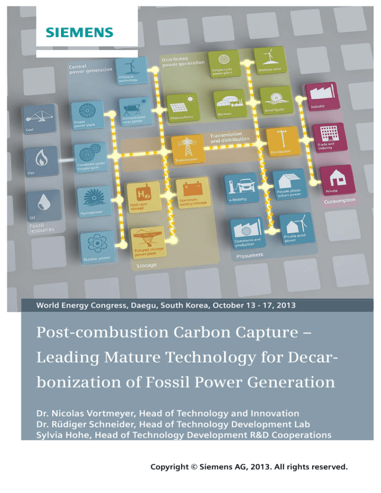
World Energy Congress, Daegu, South Korea, October 13 - 17, 2013
Post-combustion Carbon Capture –
Leading Mature Technology for Decarbonization of Fossil Power Generation
Dr. Nicolas Vortmeyer, Head of Technology and Innovation
Dr. Rüdiger Schneider, Head of Technology Development Lab
Sylvia Hohe, Head of Technology Development R&D Cooperations
Copyright © Siemens AG, 2013. All rights reserved.
World Energy Congress in Daegu, South Korea, Oct 13 - 17, 2013
1. Executive Summary
It is projected that once CCS technologies are validated and their associated costs are
proven through the operation of large-scale demonstration plants such as within the EU CCS
demonstration program, CCS will become cost-competitive with other low-carbon energy
technologies.1
Among the various available CCS technologies, post-combustion capture is the most versatile and the best adapted to the requirements of power plant operators. The PostCapTM process with its innovative solvent reclaiming system is the most benign option among the different post-combustion capture solutions offered on the market. This is due to the outstanding
properties of the solvent used, an amino acid salt solution, which has a very positive effect
on emissions from the capture process and solvent handling.
The levelized cost of electricity (LCOE) of fossil-fired power plants equipped with carbon
capture is competitive with other clean power generation technologies and, due to high
availability and flexibility, is also an attractive complement to fluctuating power generation
from renewable energies.
With the application of carbon capture for the production of CO2 for enhanced oil recovery
gaining importance, processes need to be adapted to the specific needs of gas-fired power
plants that are predominant in the relevant markets. Siemens has identified several possible
cost-reduction measures that make the PostCapTM process more cost-effective for gas-fired
power plants and that offer significant potential for cutting the costs per ton of CO2.
Keywords: Carbon capture, environment, post-combustion capture, PostCapTM, gas-fired
power plants
2. Introduction
As shown in Figure 1 below, forecasts indicate that fossil energy sources will remain the
backbone of power generation worldwide in the coming decades. While the relative share of
fossil power generation is expected to shrink slightly in the future, the absolute value of
power generation from fossil fuels will probably rise significantly. Even if power generation
from renewable sources increases sharply, fossil power generation needs to be extended in
parallel as a complementary energy source when renewable energies are not available, due
to the lack of efficient and low-cost energy storage options.
This also means that the total CO2 emissions from power generation are very likely to grow
despite worldwide efforts to reduce greenhouse gas emissions. However, there is still a
chance to reach CO2 emission reduction targets and thus the assumed maximum allowable
increase in global warming if Carbon Capture and Storage (CCS) or Carbon Capture, Utilization and Storage (CCUS) are implemented in addition to maximizing efficiency levels in
power generation. According to the International Energy Agency (IEA), CCS must provide
20% of the global cuts in CO2 emissions required by 2050.2
1
Zero emissions platform (ZEP): ”The Costs of CO2 Capture, Transport and Storage - Post-demonstration CCS in the EU,”
July 2011
2
Zero emissions platform (ZEP): “ZEP statement on CCS cost reports: Post 2020, CCS will be cost-competitive with other
low-carbon energy technologies”
Copyright © Siemens AG 2013. All rights reserved.
2
World Energy Congress in Daegu, South Korea, Oct 13 - 17, 2013
Figure 1: Global electricity market forecast for 2030 (source: Siemens)
3. Market Requirements
The forecast costs for carbon capture and storage for the first commercially operated plants
after 2020 are estimated to range between 35 and 90 €/t CO2, the capture plant contributing
at least half of the costs (see Figure 2). With very low CO2 certificate prices - currently
around 5 €/t CO2 (European Emission Allowances)3, there is still a large gap between the
costs of carbon capture and what power plant operators would be ready to pay for it. This
means that carbon capture and storage without commercial use of the CO2 such as for enhanced oil recovery is not commercially viable for the moment. Unless the CO2 can be
commercially used (CCUS – Carbon Capture, Utilization and Storage) or CO2 emission
rights become much more restricted, fossil-fired power plants will continue to be operated
without carbon capture.
Figure 2:
3
Total cost of Carbon Capture and Storage with main cost drivers
Source: www.eex.com
Copyright © Siemens AG 2013. All rights reserved.
3
World Energy Congress in Daegu, South Korea, Oct 13 - 17, 2013
Depending on the location of the storage site (onshore or offshore) as well as the transport
distance and therefore pipeline length, costs for transport and storage can vary widely. In
addition, permissions also differ for onshore and offshore storage. While onshore storage is
cheaper than offshore storage, the population of several countries such as Germany is opposed to living near a CO2 storage site.
Based on long experience in the U.S., the transport of CO2 in pipelines is not critical. The
risks are known and easily managed. Costs can be reduced by early strategic planning of
large-scale CO2 transport infrastructure, such as clustering CCS plants with a transport network. 4
CO2 storage in depleted oil and gas fields as well as in saline aquifers has been proven feasible through the operation and subsequent monitoring of CO2 storage sites both onshore
and offshore. Storage in depleted oil and gas fields is cheaper than in deep saline aquifers
and, logically, large reservoirs are cheaper to operate than smaller ones.5
At the moment, the main obstacle for market introduction is the cost of capture, mainly
driven by CO2 capture plants (see Figure 2). However, compared with other CO2 mitigation
options such as replacing fossil-fired power plants with renewable energy sources, carbon
capture becomes commercially interesting. The levelized cost of electricity (LCOE) for combined cycle power plants as well as steam power plants with carbon capture is lower than for
offshore wind and photovoltaic plants (see Figure 3). The only other CO2-free power generation options with lower LCOE are nuclear and onshore wind power plants.
Figure 3:
Comparison of levelized cost of electricity for various fossil and renewable power
plant types (source: IHS CERA)
Wind energy seems quite attractive in terms of LCOE. Yet it should be considered that
wind energy is not always available when needed and vice versa. Therefore, costs for energy storage would in fact need to be added to LCOE in order to base the total costs on
the same availability.
Furthermore, it is projected that CCS costs can be further reduced in the years to come so
that, after the European Union’s CCS demonstration program is concluded, CCS will be
4
Zero emissions platform (ZEP): ”The Costs of CO2 Capture, Transport and Storage - Post-demonstration CCS in the EU,“
July 2011
5
Zero emissions platform (ZEP): ”The Costs of CO2 Capture, Transport and Storage - Post-demonstration CCS in the EU,“
July 2011
Copyright © Siemens AG 2013. All rights reserved.
4
World Energy Congress in Daegu, South Korea, Oct 13 - 17, 2013
competitive with other sources of low-carbon power, including on- and offshore wind, solar
and nuclear power.6
Fossil-fired power plants with carbon capture can thus be seen as an ideal low-CO2 backup and complement to the use of renewable energy sources: Energy from power plants
with CCS is available when needed and has very low CO2 emissions.
Figure 4 shows that the LCOE of a fossil-fired power plant with CCS operated in base load
can be at the same level as for the same plant without CCS operated in mid-load.
Due to the impact of an increasing portion of renewable energy sources in the overall energy mix, fossil-fired power plants are required to be operated more and more flexibly in
peak load operation, i.e. with low operating hours per year. This conflicts with the interests
of CCS, since power plants with CCS require mid- to base-load operation to be competitive
due to their higher investment costs. Base-load operations of power plants with CCS therefore need to be subsidized in analogy to renewable power plants to create equal conditions.
Figure 4:
Sensitivity of LCOE by operating hours for fossil-fired power plants with CCS
This opinion is shared by the Zero Emissions Platform (ZEP), since they forecast that
base-load demand is likely to decrease while the need for balancing power wil increase in
order to complement intermittent power sources. They therefore assume the additional
need for energy storage capacity and balancing power, combined with operating thermal
power plants at lower utilization, will increase the overall cost of electricity.7
6
Zero emissions platform (ZEP): “ZEP statement on CCS cost reports: Post 2020, CCS will be cost-competitive with other
low-carbon energy technologies”
7
Zero emissions platform (ZEP): “ZEP statement on CCS cost reports: Post 2020, CCS will be cost-competitive with other
low-carbon energy technologies”
Copyright © Siemens AG 2013. All rights reserved.
5
World Energy Congress in Daegu, South Korea, Oct 13 - 17, 2013
4. Post-Combustion Carbon Capture
There are three main technology options for carbon capture: Oxyfuel combustion, precombustion capture and post-combustion capture. In oxyfuel combustion, the fuel combustion is done with pure oxygen rather than air; pre-combustion capture entails decarbonization
of the fuel gas produced in a fuel gasifier and combustion of the resulting hydrogen gas. In
post-combustion capture processes, the CO2 resulting from fuel combustion in a boiler or
gas turbine is washed out of the flue gas before it is released to the atmosphere. The principles of pre-and post-combustion CO2 capture are represented in greater detail in Figure 5
below.
Figure 5:
Schematic representation of pre- and post-combustion carbon capture
All three technology paths are being persued in pilot and demonstration projects throughout
the world and each has certain advantages in specific applications. A major advantage of
post-combustion carbon capture processes is that they can be used both for new power
plants and for retrofitting existing power plants. Post-combustion carbon capture is very
flexible in terms of fuels and the combustion process itself, which makes it more versatile
than the other two technology options. A post-combustion capture plant can be designed
either for the complete flue gas stream or for only part of it. In addition, power plants
equipped with post-combustion capture can still be operated without the capture plant, i.e. if
required, the capture plant can be bypassed. This option does not exist for the two other
technology paths.
Pre-combustion capture is most suitable for new IGCC power plants combined with the polygeneration of chemical products. In addition to a combined cycle power plant equipped
with a gas turbine running on hydrogen instead of natural gas, the set-up requires a fuel
gasifcation plant and a chemical plant with several cleaning and conversion steps for the
synthesis gas produced in the gasifier, including a CO2 capture plant that uses physical absorption. For mere power generation without being able to use by-products in a neighbouring
chemical plant, IGCCs with carbon capture are probably too complex.
Post-combustion capture is therefore the most suitable and flexible option for power generation and at the same time the most benign solution.
Copyright © Siemens AG 2013. All rights reserved.
6
World Energy Congress in Daegu, South Korea, Oct 13 - 17, 2013
5. PostCapTM Technology
Siemens has developed a proprietary post-combustion carbon capture technology named
PostCapTM. The primary targets for Siemens in the development of the PostCapTM process
were to meet most stringent environmental requirements without compromising the economics. At the same time, Siemens as a power plant provider followed the principle that “a power
plant remains a power plant;” it was considered that the operating staff at the power plant
can handle the plant operation according to their accustomed safety standards.
Siemens therefore decided in favor of amino acid salts (AAS) as the basis for the process
because the physical and chemical properties of AAS have advantages compared to amine
solvents with respect to solvent handling, plant operation and operating permissions. AAS
are chemically stable and naturally present. They have ionic structure in the solution, which
provides substantial advantages such as virtually zero vapour pressure, therefore nearly
zero solvent emissions, high absorption capacity, negligible degradation, low energy consumption and environmental sustainability compared to other amine-based technologies in
this field. In addition, amino acid salts have a low sensitivity to oxygen degradation due to
their structure. Since salts do not have vapour pressure, they are very easy to handle: They
are not inflammable or explosive and do not present an inhalation risk. In addition, they have
a high biodegradability, are nontoxic and environmentally friendly.
The Siemens PostCap™ technology utilizes selective absorption of the CO2 from the flue
gas and subsequent desorption, thus gaining nearly pure CO2. An improved process configuration is applied, resulting in a significant reduction of energy demand. The low solvent
degradation through O2 contained in the flue gas as well as through elevated temperatures
leads to reduced solvent consumption of the process. The low energy demand for the solvent regeneration (i.e. 2.7 GJ thermal per tonne of CO2 captured) and the possibility of running the process at various temperature and pressure conditions makes the proposed design exceptional. The solvent is nontoxic, biodegradable and has negligible vapour pressure.
As a result, solvent losses and emissions in the cleaned flue gas and the separated CO2
stream are below practicable detection limits.
The main components in the CO2 capture plant (i.e. PostCap™ Plant) are the absorption
and desorption columns (see Figure 6). The absorber and desorber column internals in particular are essential for the efficient and reliable operation of the carbon capture plant. A
broad range of column internals has been evaluated during the past years to select the optimal internals for the absorption and desorption process. Process design parameters such
as temperature etc. are set so that the precipitation of solid salts is avoided. During more
than 7,000 hours of pilot operation, no plugging of trays or packings was observed.
Figure 6:
PostCapTM process with solvent reclaiming
Copyright © Siemens AG 2013. All rights reserved.
7
World Energy Congress in Daegu, South Korea, Oct 13 - 17, 2013
The standard desorber design considers atmospheric pressure conditions at the desorber
outlet. If required, the design can be changed to elevated pressures. A CO2 compressor
would bring the gaseous CO2 up to higher pressure for further processing. Appropriate units
for CO2 purification are available to meet needs such as pipeline transportation and storage
with respect to water and oxygen content.
A great advantage of amino acid salt solvents is that the solvent does not evaporate and
therefore is not emitted with the cleaned flue gas as a solvent slip (below detection limit of
even very sensitive measurement instruments). Since the solvent is chemically and thermally very stable (see subsequent paragraphs), only very small amounts of solvent degradation products are emitted. These occur in a much lower amount than for amine-based solvents and comply with the most stringent environmental requirements.
The aqueous amino acid salt solution used as solvent exhibits low thermal sensitivity, so that
solvent degradation is relatively low. The thermal stability of the solvent has been proven in
short- and long-term investigations. Amino acid salts have an ionic structure and therefore a
low susceptibility to oxygen degradation. Oxygen dissolved in water tends to negative loading and is thus hindered in degrading the dissolved anion of the amino acid salt. This results
in a high chemical stability.
Nevertheless, due to the fact that in post-combustion processes large quantities of flue gas
are treated over a long period of time, even very small amounts of trace components which
are contained in the flue gas as secondary components (like sulphur- or nitrogen oxides)
could lead to a noticeable accumulation of secondary products in the solvent pump-around.
These secondary products (heat-stable salts, HSS) also have negligible vapour presure and
are therefore not evaporated in the desorber. In order to prevent an accumulation in the solvent cycle, these components must be eliminated by continuously removing a minor part of
the solvent in a purge stream. Therefore, a purge stream of the cold solvent is directed to a
reclaimer unit, where secondary products are removed. The removed solvent is replaced by
the same amount of fresh solvent or of regenerated solvent from the reclaiming operation.
Reclaimer concepts for amine-based solvents are not suitable for amino acid salts since they
rely on evaporating the active component. Since salts cannot be evaporated, however, Siemens has developed a proprietary process for reclaiming amino acid salt solvents.
The solvent reclaiming unit, as shown in Figure 6, ensures that the utilization of solvent is
maximized and solvent residues are minimized, and thus contributes to the substantially low
operational costs. Furthermore, through the reclaimer, sulphur oxides contained in the flue
gas are converted to a marketable fertilizer product. Therefore, the requirements for limiting
the SOx levels upstream of the absorber are less strict compared to other amine-based capture technologies.
6. Challenges for Carbon Capture Plants in the Middle East
As a result of available commercial boundary conditions, CO2 capture for use in enhanced
oil recovery (EOR) projects has recently grown in importance. Post-combustion capture
technology is increasingly being applied to CO2 capture from gas-fired power plants. Figure
7 visualizes major impacts and challenges when implementing CO2 capture at gas-fired
power plants in comparison to coal-fired steam power plants. Flue gas from gas-fired power
plants is particularly challenging due to several factors: The CO2 concentration in the flue
gas is significantly lower than for coal-fired power plants, while the O2 concentration is much
higher. In addition, the flue gas mass flow per MWel is approximately 60% higher in gas-fired
power plants.
Copyright © Siemens AG 2013. All rights reserved.
8
World Energy Congress in Daegu, South Korea, Oct 13 - 17, 2013
Figure 7:
Major impacts and challenges for post-combustion carbon capture with gas fired
combined cycle power plants (CCPP) vs. steam power plants (SPP)
The lower CO2 content implies lower solvent loading and slower reaction kinetics, leading to
a higher specific energy demand for regeneration and higher absorption columns. On the
other hand, the higher O2 content in the flue gas leads to a higher solvent degradation and
therefore to an increased reclaiming need and solvent consumption. Yet, amino-acid salt
solvents are especially well-suited for high O2 contents since they have low susceptibility to
oxygen-induced degradation due to their chemical structure. The higher specific flue gas
mass flow makes it necessary to use larger absorber diameters.
Overall, capture costs per ton of CO2 are thus higher for gas-fired power plants than for coalfired power plants. Yet, countries where CO2 can be commercially used for enhanced oil or
gas recovery usually operate gas-fired power plants, since the fuel is locally available. The
reduction of costs per ton of CO2 captured is therefore the main target for making carbon
capture more attractive in regions such as the Middle East.
The main investment cost contributors for a carbon capture plant in the Middle East are the
absorption columns (due to the large flue gas volumes), the CO2 compressor, the flue gas
cooler (direct contact cooler, DCC) and the desorption column. In addition, high purity of the
produced CO2 is generally required, so that a CO2 purification step must be included. The
main cost reduction levers and thus improvement potential identified for Siemens’ carbon
capture process are therefore the absorption and desorption columns as well as the direct
contact cooler.
Copyright © Siemens AG 2013. All rights reserved.
9
World Energy Congress in Daegu, South Korea, Oct 13 - 17, 2013
Figure 8:
3D view of a gas-fired combined cycle power plant with PostCapTM Plant with two
absorption lines
Figure 8 shows an example of a 700-MW natural gas-fired combined cycle power plant with
4,500 TPH flue gas with 6%wt CO2. The scheduled CO2 production is 1,800,000 TPA of CO2
@ 200 bar. Siemens has done a FEED study for this project with the aim of retrofitting a single-train PostCapTM Plant with two absorption lines to an existing power plant.
This 3D views shows the large dimensions of the direct contact cooler, the possible omission
of which is described as a cost reduction option in the following section.
7. Cost Reduction Potential
As a result of lower CO2 and higher O2 concentrations as well as larger flue gas quantities,
the specific cost for separating a certain amount of CO2 is significantly increased compared
to coal-fired power plants. In order to be able to implement a capture project successfully in
the market, the capture cost needs to be dramatically reduced. In our own investigations
based on FEED studies for various customers, Capital Expenditures (CAPEX) in particular
have been identified as the major lever for cost reduction. However, Operational Expenditures (OPEX) must also be taken into account since both cost shares are associated with
one other.
Several process elements can be improved or modified in order to enhance cost effectiveness. The most promising cost reduction potential has been found in the following upgrades:
Reduction of required component sizes and capacities by improving capture chemistry and/or reducing concept complexity
Innovative cycles, such as improving energy utilization and/or flue gas properties
(e.g. increase of partial CO2 pressure)
In the following , the cost reduction potential is exemplified with specific possible measures.
a) Reduction of concept complexity and component sizes:
Solvent activators:
Additional CAPEX savings of up to 5-10 % can be achieved by applying enhanced solvent
activators. This would accelerate reaction kinetics which would result in lower heights for the
absorber and desorber columns. Initial results show a reduction potential of column heights
of about 20 % by applying an enhanced activator dedicated to the AAS solvent used in the
PostCap™ process.
Copyright © Siemens AG 2013. All rights reserved. 10
World Energy Congress in Daegu, South Korea, Oct 13 - 17, 2013
Construction materials:
And additional 5 - 10% CAPEX savings can be achieved by further optimizing construction
materials used in the capture plant. Comprehensive long-term investigations are under way
to judge the applicability of lower-grade materials for PostCap™. With the qualification of a
number of materials for different plant parts and equipments, material selection can be optimized with regard to availability and market prices. Where reasonable, the adaptation of
certain operating and design parameters of the PostCap™ process is taken into account to
enable the use of cheaper materials.
Solvent precipitation:
Conventionally, absorption/desorption processes will be operated in liquid phase only; i.e.
process conditions will be chosen in such a way that no reaction products of the CO2 with
solvent precipitate. However, precipitation enables higher rich loadings and a more efficient
desorption. The reduced energy demand results will directly reduce CAPEX due to smaller
desorber diameters and heat exchangers. Nevertheless, a process including a precipitation
step would require special equipment that might increase CAPEX. As a result of a conceptual process evaluation, OPEX can be decreased by about 20% and thus decrease total CO2
capture cost.
b) Innovative cycles:
As a result of the lower CO2 content in the exhaust gas of gas fired power plants, specific
costs for the production of one ton of CO2 are high in comparison to coal-fired power plants.
It is therefore obvious that these costs can be decreased by increasing the CO2 concentration. Several concepts have been and will be evaluated utilizing processes such as the supplementary combustion of flue gas. Besides increasing CO2 content, this would decrease the
oxygen amount contained in the flue gas and therefore the degradation of solvent.
In the past, CO2 capture was mainly foreseen as a retrofit to existing power plants. As an
experienced supplier of power plants and at the same time as technology owner of the PostCap™ technology, Siemens undertook comprehensive studies for optimally integrating the
capture plant into the power plant environment so waste heat can be utilized as efficiently as
possible. Additional potential for decreasing CAPEX and OPEX was identified by modifying
the power plant so the integration of the carbon capture facilities can be optimized. As a result, the total cost for operating the power plant and capture plant entity can be reduced.
Possible concepts hint at a better utilization of sensible heat contained in the flue gas, such
as desorber heating or increasing the flue gas pressure.
As a preliminary result, specific CO2 separation costs at gas-fired power plants can be decreased by 10% to 20%.
8. Conclusions and Relevant Implications
Several carbon capture technologies from a multitude of suppliers have been developed and
are ready for large-scale Implementation. The levelized cost of electricity (LCOE) produced
with fossil-fired power plants equipped with carbon capture is already lower now than with
offshore wind or photovoltaic power generation. Through further cost reduction measures
and the experience gained in large-scale demonstration projects, the LCOE of power plants
with CCS are expected to become competitive with other low-carbon power generation options such as onshore wind and nuclear power plants.
Among the various available post-combustion carbon capture technologies, Siemens’ PostCapTM occupies an exceptional position since other suppliers use amines or ammonia as a
solvent, while Siemens uses an amino-acid salt (AAS) solution. AAS are non-volatile, which
is a major advantage in terms of emissions and solvent handling, but also requires a specific
reclaiming process for the regeneration of used solvent. Siemens has therefore developed a
Copyright © Siemens AG 2013. All rights reserved. 11
World Energy Congress in Daegu, South Korea, Oct 13 - 17, 2013
proprietary reclaiming process that complements the PostCapTM carbon capture process
and significantly reduces operational costs.
As a power plant provider, Siemens is well aware of the requirements of power plant operators and could therefore tailor its PostCapTM process to their needs. Specific technologies
and competencies are required for developing a suitable carbon capture technology for
power plants. Using a post-combustion capture plant with PostCapTM technology, no new
safety standards would have to be observed by the operating staff, and permits would be
easily obtained. The interests of power plant operators have been in the focus of PostCapTM development, and will remain in Siemens’ focus for all process optimization measures.
Since the production of CO2 for Enhanced Oil Recovery (EOR) in oil- and gas-producing
countries is becoming increasingly important as an application for carbon capture, cost reduction measures need to concentrate on applications for gas-fired power plants. Considering the specific characteristics of flue gas from gas-fired power plants such as low CO2 concentration, Siemens is emphasizing the development of measures that specifically address
the requirements of gas-fired power plants.
With regard to carbon capture with storage, that is without commercial use of the produced
CO2, greater incentives are necessary for power plant operators to invest in CCS. Since CO2
certificate prices in the European Trading Scheme remain very low, the ETS alone does not
promote the construction of carbon capture plants in Europe. If we consider the major role
that CCS is generally agreed to play in the efforts to limit global warming to 2°C, the investment risk for power plants with CCS has to be reduced worldwide.
Copyright © Siemens AG 2013. All rights reserved. 12
World Energy Congress in Daegu, South Korea, Oct 13 - 17, 2013
Permission for use
The content of this paper is copyrighted by Siemens and is licensed to the WEC for publication and distribution only. Any inquiries regarding permission to use the contents of this paper, in whole or in part, for any purpose must be addressed to Siemens directly.
Disclaimer
These documents contain forward-looking statements and information – that is, statements
related to future, not past, events. These statements may be identified either orally or in writing by words as “expects”, “anticipates”, “intends”, “plans”, “believes”, “seeks”, “estimates”,
“will” or words of similar meaning. Such statements are based on our current expectations
and certain assumptions, and are, therefore, subject to certain risks and uncertainties. A
variety of factors, many of which are beyond Siemens’ control, affect its operations, performance, business strategy and results and could cause the actual results, performance or
achievements of Siemens worldwide to be materially different from any future results, performance or achievements that may be expressed or implied by such forward-looking statements. For us, particular uncertainties arise, among others, from changes in general economic and business conditions, changes in currency exchange rates and interest rates, introduction of competing products or technologies by other companies, lack of acceptance of
new products or services by customers targeted by Siemens worldwide, changes in business strategy and various other factors. More detailed information about certain of these
factors is contained in Siemens’ filings with the SEC, which are available on the Siemens
website, www.siemens.com and on the SEC’s website, www.sec.gov. Should one or more of
these risks or uncertainties materialize, or should underlying assumptions prove incorrect,
actual results may vary materially from those described in the relevant forward-looking
statement as anticipated, believed, estimated, expected, intended, planned or projected.
Siemens does not intend or assume any obligation to update or revise these forward-looking
statements in light of developments which differ from those anticipated.
Trademarks mentioned in these documents are the property of Siemens AG, its affiliates or
their respective owners.
Copyright © Siemens AG 2013. All rights reserved. 13

