Time-stepping beyond CFL: a locally one-dimensional scheme for acoustic wave...
advertisement
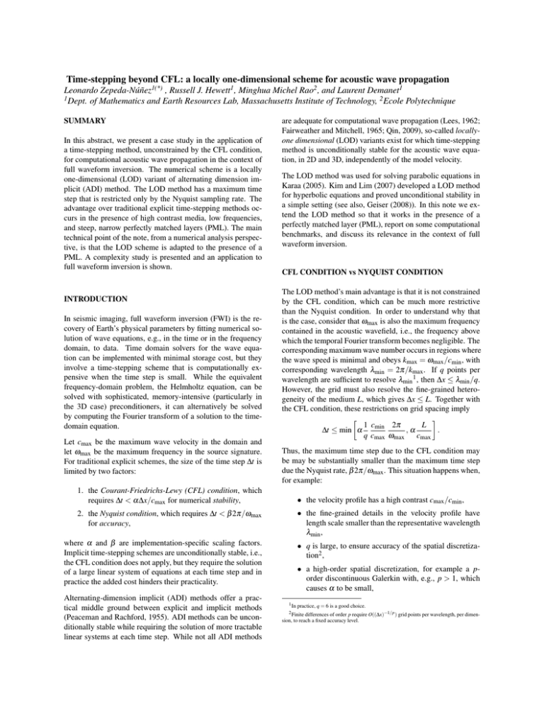
Time-stepping beyond CFL: a locally one-dimensional scheme for acoustic wave propagation Leonardo Zepeda-Núñez1(*) , Russell J. Hewett1 , Minghua Michel Rao2 , and Laurent Demanet1 1 Dept. of Mathematics and Earth Resources Lab, Massachusetts Institute of Technology, 2 Ecole Polytechnique SUMMARY In this abstract, we present a case study in the application of a time-stepping method, unconstrained by the CFL condition, for computational acoustic wave propagation in the context of full waveform inversion. The numerical scheme is a locally one-dimensional (LOD) variant of alternating dimension implicit (ADI) method. The LOD method has a maximum time step that is restricted only by the Nyquist sampling rate. The advantage over traditional explicit time-stepping methods occurs in the presence of high contrast media, low frequencies, and steep, narrow perfectly matched layers (PML). The main technical point of the note, from a numerical analysis perspective, is that the LOD scheme is adapted to the presence of a PML. A complexity study is presented and an application to full waveform inversion is shown. INTRODUCTION In seismic imaging, full waveform inversion (FWI) is the recovery of Earth’s physical parameters by fitting numerical solution of wave equations, e.g., in the time or in the frequency domain, to data. Time domain solvers for the wave equation can be implemented with minimal storage cost, but they involve a time-stepping scheme that is computationally expensive when the time step is small. While the equivalent frequency-domain problem, the Helmholtz equation, can be solved with sophisticated, memory-intensive (particularly in the 3D case) preconditioners, it can alternatively be solved by computing the Fourier transform of a solution to the timedomain equation. Let cmax be the maximum wave velocity in the domain and let ωmax be the maximum frequency in the source signature. For traditional explicit schemes, the size of the time step ∆t is limited by two factors: are adequate for computational wave propagation (Lees, 1962; Fairweather and Mitchell, 1965; Qin, 2009), so-called locallyone dimensional (LOD) variants exist for which time-stepping method is unconditionally stable for the acoustic wave equation, in 2D and 3D, independently of the model velocity. The LOD method was used for solving parabolic equations in Karaa (2005). Kim and Lim (2007) developed a LOD method for hyperbolic equations and proved unconditional stability in a simple setting (see also, Geiser (2008)). In this note we extend the LOD method so that it works in the presence of a perfectly matched layer (PML), report on some computational benchmarks, and discuss its relevance in the context of full waveform inversion. CFL CONDITION vs NYQUIST CONDITION The LOD method’s main advantage is that it is not constrained by the CFL condition, which can be much more restrictive than the Nyquist condition. In order to understand why that is the case, consider that ωmax is also the maximum frequency contained in the acoustic wavefield, i.e., the frequency above which the temporal Fourier transform becomes negligible. The corresponding maximum wave number occurs in regions where the wave speed is minimal and obeys kmax = ωmax /cmin , with corresponding wavelength λmin = 2π/kmax . If q points per wavelength are sufficient to resolve λmin 1 , then ∆x ≤ λmin /q. However, the grid must also resolve the fine-grained heterogeneity of the medium L, which gives ∆x ≤ L. Together with the CFL condition, these restrictions on grid spacing imply 1 cmin 2π L ∆t ≤ min α ,α . q cmax ωmax cmax Thus, the maximum time step due to the CFL condition may be may be substantially smaller than the maximum time step due the Nyquist rate, β 2π/ωmax . This situation happens when, for example: 1. the Courant-Friedrichs-Lewy (CFL) condition, which requires ∆t < α∆x/cmax for numerical stability, • the velocity profile has a high contrast cmax /cmin , 2. the Nyquist condition, which requires ∆t < β 2π/ωmax for accuracy, • the fine-grained details in the velocity profile have length scale smaller than the representative wavelength λmin , where α and β are implementation-specific scaling factors. Implicit time-stepping schemes are unconditionally stable, i.e., the CFL condition does not apply, but they require the solution of a large linear system of equations at each time step and in practice the added cost hinders their practicality. • q is large, to ensure accuracy of the spatial discretization2 , Alternating-dimension implicit (ADI) methods offer a practical middle ground between explicit and implicit methods (Peaceman and Rachford, 1955). ADI methods can be unconditionally stable while requiring the solution of more tractable linear systems at each time step. While not all ADI methods • a high-order spatial discretization, for example a porder discontinuous Galerkin with, e.g., p > 1, which causes α to be small, 1 In practice, q = 6 is a good choice. p require O((∆x)−1/p ) grid points per wavelength, per dimension, to reach a fixed accuracy level. 2 Finite differences of order LOD Methods • a grid with high spatial resolution is used to solve a low frequency problem, for which the Nyquist rate is now β 2π/ω with ω < ωmax , boundary conditions, the LOD scheme is h e h n m − η∆t 2 δxx u = m 2un − un−1 + ∆t 2 δxx uη + fn , • a PML is used to approximate absorbing boundary conditions, causing an additional constraint on ∆t linked to the strength of the absorption in the layer. As a consequence, using the LOD scheme for time-stepping allows problems with high velocity contrasts, sharp medium heterogeneities, accurate discretizations, or steep PMLs, to be solved without further penalty on the time step. LOD FORMULATION In this paper we restrict ourselves to two spatial dimensions. Let u(x,t) be the solution of the acoustic wave equation, with constant density, given by m(x)∂tt u(x,t) = 4u(x,t) + f (x,t), (1) u(x, 0) = 0, (2) ∂t u(x, 0) = 0, (3) where x = (x, z), m(x) = 1/c2 (x) is the model with units of squared slowness, and f (x,t) = g(x)w(t) is a separable source with point impulse g and essentially bandlimited wavelet w. For now, we disregard spatial boundary conditions. Without loss of generality, we assume that ∆x = ∆z. While there are many different approaches for discretizing (1)– (3), in this paper we use finite differences to approximate the derivatives both in time and in space. Let t n = n∆t and h = ∆x, and let un and m be the discrete approximations of u(x,t n ) h , and δ h be spatial and m(x), respectively. Let δxh , δzh , δxx zz finite difference operators, of order p, for the first (x and z) and second derivatives (xx and zz). Then, the simplest explicit time-stepping scheme for approximating solutions to (1) is h mun+1 = m 2un+1 − un−1 + ∆t 2 (δxx + δzzh )un + fn , (4) which is second order accurate in time when u is smooth enough. Each time step in this scheme is computationally inexpensive, requiring only O(N) floating point operations and O(N) storage, where N = Nx × Nz is the number of unknowns. However, this scheme is limited by the CFL condition. Implicit methods operate on the principle that the terms involving spatial differences can also be evaluated at time t n+1 , which results in a linear system of equations for un+1 . ADI methods split the time step into two or more sub-steps and treat a single dimension implicitly in each sub-step. As a result, the linear systems due to the implicit part are simple, tightly banded systems. The LOD method we describe in this article has similar structure, but the sub-steps are conceptually different. Disregarding (5) m − η∆t 2 δzzh n+1 u = me u + ∆t 2 δzzh unη , (6) where η is a constant, unη = ((1 − 2η)un + ηun−1 ). This LOD scheme is unconditionally stable if η > 0.25 (Geiser, 2008). In contrast to traditional ADI methods (Lees, 1962; Fairweather and Mitchell, 1965), the sub-step solution e u is not a solution at t n+1/2 , rather, it is a full step approximation of the solution at t n+1 , which is then corrected by (6). Moreover, the LOD method use information from a single derivative term at each step, whereas ADI methods usually involve information from both derivative terms at each half time-step. The LOD scheme is easily extended to 3D, by adding a third equation to (5) and (6), to account for the correction in y. The stability condition on η remains unchanged in the 3D case. LOD formulation with PML Open boundary conditions for wave equations are approximated by an absorbing condition on the boundary of the computational domain. A naive truncation of the domain introduces unphysical reflections that pollute the solution and cause severe imaging artifacts. One approach for mitigating unphysical reflections is to pad the domain with an absorption layer. An efficient realization of such a scheme is the perfectly matched layer (PML), introduced by Bérenger (1994). The PML approach involves complex coordinate stretching, which results in the introduction of auxiliary wavefields to absorb the energy of the outgoing wave. Because it requires fewer auxiliary wavefields, we consider the PML method for the scalar wave equation introduced by Sim (2010), m (∂tt u + σx+z ∂t u + σxz u) = 4u + ∂x φx + ∂z φz + f , (7) ∂t φx = −σx φx + σz−x ∂x u, (8) ∂t φz = −σz φz + σx−z ∂z u, (9) φx (x, 0) = 0, φz (x, 0) = 0, u(x, 0) = 0, ∂t u(x, 0) = 0, (10) where σx and σz are the PML profile functions, σxz = σx σz , σx+z = σx +σz , etc., and φx and φz are the auxiliary wavefields. LOD solver for the wave equation with PML We extend the LOD solver in (5) and (6) to the PML-augmented scalar wave equation in (7)–(10). Discretizing (7)–(10) as before leads to a system of equations for u and the the discrete auxiliary wavefields, φ x and φ z . In the PML formulation, the evolution equations for φ x and φ z involve spatial operators only in x and in z, respectively. Thus, with the auxiliary fields already decoupled and the property that the LOD method treats dimensions independently, we formulate a decoupled system defined by the operators h m − η∆t 2 δxx −∆t 2 δxh x L = , (11) −∆tησz−x δxh I + γx m(I + γx+z ) − η∆t 2 (δzzh − mσxz ) −∆t 2 δzh Lz = , (12) −∆tησx−z δzh I + γz LOD Methods in which Lx and Lz contain only spatial differences in x and in z respectively, and where γx = ∆tσx /2, γz = ∆tσz /2, and γx+z = ∆tσx+z /2. The complete LOD scheme for the PML formulation is h un + fn e m(2un − un−1 ) + ∆t 2 δxx u η Lx = φ n+1 (1 − γx ) φ nx + ∆tσz−x δxh unη x Lz un+1 φ n+1 z = me u + ∆t 2 δzzh − mσxz unη + γx−z un−1 (1 − γz ) φ nz + ∆tσx−z δzh unη (13) , (14) where γx−z = ∆tσx−z /2. For η > 0.25, we claim that this scheme is stable, provided that ∆t < 1/ max (kσx k`∞ , kσz k`∞ ). The first restriction is from the boundary-free LOD scheme and the second condition is due to the stiffness of the evolution equations ((8) and (9)) for φx and φz . As a result, the LOD method for the wave equation with PML is no longer unconditionally stable, but the stability requirement due to the PML does not involve the grid spacing h, hence the restriction is very mild when compared to the original CFL condition. Efficient inversion The matrices defined in (11) and in (12) are expensive to invert as is. Precomputing the inverse requires a large amount of memory because of fill-in. To overcome this difficulty, we precompute the inverse of the Schur complement as a sparse banded matrix. For A B L= , (15) C D we have LSchur = A − BD−1C. (16) Using (16), a closed form expression for the inverse of an operator in the form of (15) (e.g., (11) and in (12)) is −1 I 0 I −BD−1 LSchur 0 L−1 = . −1 −D C I 0 I 0 D−1 (17) −1 The block involving LSchur is not necessarily sparse and may be difficult to evaluate, but when D is diagonal and A, B, and C are sparse and tightly banded, as in (11) and in (12), the Schur complement is also sparse and tightly banded. Thus, for our formulation, the LU factorization of (16) is sparse for both Lx and Lz . In practice, solving the Schur complement is done by two back-substitutions using the precomputed LU factors, which are stored in O(N) memory. As a result, the complexity of solving (13) and (14) in each time step is O(N) and the new method has the same asymptotic complexity as the explicit scheme. In the next section, we examine complexity in more detail. The explicit time-stepping scheme (with PML) requires three sparse matrix-vector products, of size at most N + M × N + M, where M is the number of new degrees of freedom added due to the PML and auxiliary wavefields, and a negligible number of vector arithmetic operations. M is usually a percentage of N, so we consider the cost of the explicit method to be O(N), per time step3 . The dominant cost for the LOD method is in the 2Nx + 2Nz back substitutions, each of which has a respective cost of O(Nz ) and O(Nx ). When combined with a non-negligible number of vector arithmetic operations and a few smaller sparse matrixvector products, the overall cost is still O(N), but the constant is larger. The explicit time-stepping scheme (with PML) requires three wavefields per time index (u, φx and φz ), and three time snapshots for second order accuracy in time. Additionally, the three sparse update matrices must be stored, at O(N) storage cost. The LOD method requires one additional wavefield (e u) and 16 sparse matrices, with a maximum number of nonzeros per row that depends on the spatial accuracy of the finite difference approximation (e.g., 5 for fourth-order accuracy). To understand the range of grid spacing ∆x and frequency ωmax at which the LOD method would provide an advantage over traditional explicit time-stepping, we apply both methods to the left 22km of the 2004 BP Velocity-Analysis Benchmark (Billette and Brandsberg-Dahl, 2005) with ∆x = ∆z = 12.5, 25, 50, and 100 m and compare the runtime per time step. The data shown are for ∆t determined by the CFL condition with α = 1/6. The same ∆t was used for both methods so the number of time steps remained constant and both methods are fourthorder accurate in space. All results in this paper are obtained using the authors’ Python Seismic Imaging Toolbox (PySIT). The results in Figure 1 are for final time T = 5s and averaged over 25 runs per grid scale. Empirically, our implementation of the LOD is approximately r = 3.25 times slower than the explicit method per time step. When to use LOD The LOD method is favored over an explicit method when the smaller overall number of time steps compensates for the additional stepwise complexity. This situation is illustrated in Figure 2, where for cmin = 1500 m/s, cmax = 4500 m/s, α = 1, β = 1/6, q = 6, and r = 3.25 we consider the valid ranges for ∆t and ∆x for the explicit and LOD methods at ωmax = 15π 0 (resp. ωmax = 6π). In region A (resp. A0 ), the explicit method is stable and in region B (resp. B0 ) the LOD method is valid, but the explicit method is more efficient, even at smaller ∆t. In region C (resp. C0 ), the LOD method is faster than the explicit method. When r ≤ βq 1 cmax , α cmin (18) region C extends below the diagonal and we have that the LOD method is always favored over an explicit method. RESULTS Complexity 3 Sparse matrix-vector products have complexity O(N + nnz), for matrices with N rows r r and nnz non-zeros. For this problem, both are on the order of N. LOD Methods 2πβ ω 0.05 0 ∆t (s) Figure 3 shows the solution to the Helmholtz equation, computed by the Fourier transform of the wavefields determined by the explicit and LOD methods. We used a single 2.5 Hz Ricker wavelet source in the left 22 km of the BP model, with PML boundaries on all sides and a free surface boundary on top. The LOD experiment had equivalent computational cost but required over a third fewer time steps. At higher resolution, the cost reduction is magnified. At low frequency, the two solutions are virtually indistinguishable. At higher frequency, there are differences that we attribute to differing levels of numerical dispersion in the two methods. ω0 C0 0.03 2πβ ω C 0.01 0 Application to Imaging For this numerical experiment, we use our LOD solver to recover a 370 × 170 patch of the Marmousi2 p-wave velocity model (G. Martin and Marfurt, 2006). We use 24 sources and 360 receivers, equispaced at the top of the domain with a Ricker wavelet centered at 7.5 Hz. The time-domain leastsquares misfit objective function was reduced by approximately two orders of magnitude in 50 L-BFGS iterations from a linearly increasing gradient initial model. The simulated measured data are computed via the explicit method with a smaller time step to prevent the so-called inverse crime. The true model, initial model, and final reconstruction are shown in Figure 4. B0 ω B A A0 25 2πcmin 50 ωq ∆x (m) 75 2πcmin ω0 q Figure 2: Boxes for ω = 15π (resp. ω 0 = 6π) correspond to sampling restrictions in time and space. Region A (resp. A0 ) satisfies the CFL stability condition ∆t ≤ α∆x/cmax , region B (resp. B0 ) has LOD method valid, but slower than explicit method with smaller ∆t, region C (resp. C0 ) has LOD method more efficient than explicit method. (a) explicit CONCLUSION We present a locally one-dimensional (LOD) solver for the scalar time-dependent wave equation with PML boundary conditions. The method has very favorable stability properties not restricted by the CFL condition. It can be an efficient alternative to explicit time-stepping, e.g., in settings of low frequencies or high velocity contrasts. We demonstrate the potential of the LOD method by contrasting it to an explicit method for the numerical solution of the Helmholtz equation. Full waveform inversion tests also validate the solver. (b) LOD Figure 3: Real part of solution to the Helmholtz equation at 2 Hz, computed by discrete Fourier transform of temporal wavefields from (a) explicit method and (b) LOD method. LOD method is computed with 3 times fewer time steps. ACKNOWLEDGEMENTS time step cost (s) The authors thank Total SA for supporting this research. LD is also grateful to the National Science Foundation and the Alfred P. Sloan Foundation. The 2004 BP Velocity-Analysis Benchmark model was provided courtesy of BP and Frederic Billette. 100 10-1 LOD O(N) (a) True (b) Initial explicit 10-2 105 N 106 Figure 1: Run time per time step for explicit (green) and LOD (blue) as function of number of unknowns. (c) Final Figure 4: (a) True, (b) initial, and (c) recovered model from time-domain full waveform inversion, using LOD solver, after 50 L-BFGS iterations. LOD Methods REFERENCES Bérenger, J.-P., 1994, A perfectly matched layer for the absorption of electromagnetic waves: J. C. P., 114. Billette, F., and S. Brandsberg-Dahl, 2005, The 2004 BP velocity benchmark.: EAGE. Fairweather, G., and A. Mitchell, 1965, A high accuracy alternating direction method for the wave equation: IMA Journal of Applied Mathematics, 1(4). G. Martin, R. W., and K. Marfurt, 2006, An elastic upgrade for Marmousi: The Leading Edge, Society for Exploration Geophysics, 25. Geiser, J., 2008, Fourth-order splitting methods for timedependent differential equations: Numer. Math. Theor. Meth. Appl., 1(3). Karaa, S., 2005, An accurate LOD scheme for twodimensional parabolic problems: Appl. Math. Comput., 170. Kim, S., and H. Lim, 2007, High-order schemes for acoustic waveform simulation: Appl. Numer. Math., 57. Lees, M., 1962, Alternating direction methods for hyperbolic differential equations: J. SIAM, 10(4). Peaceman, D., and H. Rachford, 1955, The numerical solution of parabolic and elliptic differential equations: J. SIAM, 3(1). Qin, J., 2009, The new alternating direction implicit difference methods for the wave equations: J. Comput. Appl. Math., 230(1). Sim, I., 2010, Nonreflecting boundary conditions for the timedependent wave equation: PhD thesis, University of Basel.
