SITE PLANNING DATA—LIEBERT® EXL™ 625-1200KVA SINGLE-MODULE AND 1+N SYSTEMS
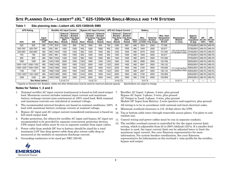
Table 1
Site planning data—Liebert eXL 625-1200kVA SMS
UPS Rating
Rectifier AC Input Current
Bypass AC Input Current
UPS AC Output Current
Battery
External External
External External
External External
Breaker Breaker
Breaker Breaker
Breaker Breaker
Max. Heat
Trip Amp Trip Amp
Trip Amp Trip Amp
Trip Amp Trip Amp
Max.
External Dissipation
Input
(80%
(100%
(80%
(100%
(80%
(100% Nom, Current Breaker
Full Load
Voltage
Rated) Nom Rated)
Rated) Nom Rated)
Rated) VDC at EOD Trip Amps
BTU/H
VAC Nom Max Rated)
Dimensions
WxDxH
in (mm)
Approx.
Weight
Eff.
Eff.
Unpacked AC-AC DC-AC
lb (kg)
100% 100%
kVA
kW
625
625
480
779
818
1200
900
752
1000
800
752
1000
800
480
1624
2000
77,348
5735(2601) ≥96.5% ≥96.5%
625-750*
625-750*
480
935
981
1400
1000
902
1200
1000
902
1200
1000
480
1949
2000
92,817
5735(2601) ≥96.4% ≥96.4%
625-800*
625-800*
480
995 1044
1400
1200
962
1200
1000
962
1200
1000
480
2079
2500
101,940
750
750
480
935
1400
1000
902
1200
1000
902
1200
1000
480
1949
2000
92,817
125.2x33.5x76.8
(3145x850x1950) 5735(2601) ≥96.5% ≥96.5%
5735(2601) ≥96.5% ≥96.5%
5735(2601) ≥96.4% ≥96.4%
981
800
800
480
995 1044
1400
1200
962
1400
1000
962
1400
1000
480
2079
2500
101,940
1000
1000
480
1244 1308
2000
1600
1203
1600
1400
1203
1600
1400
480
2588
3000
123,756
8050(3651) ≥96.5% ≥96.5%
1000-1100* 1000-1100*
480
1368 1438
2000
1600
1323
2000
1400
1323
2000
1400
480
2847
3000
136,132
8050(3651) ≥96.4% ≥96.4%
1000-1200* 1000-1200*
480
1493 1569
2000
1600
1443
2000
1600
1443
2000
1600
480
3106
4000
152,909
480
1368 1438
2000
1600
1323
2000
1400
1323
2000
1400
480
2847
3000
136,132
171.7x33.5x76.8 8050(3651) ≥96.5% ≥96.5%
(4330x850x1950) 8050(3651) ≥96.5% ≥96.5%
480
1493 1569
2000
1600
1443
2000
1600
1443
2000
1600
480
3106
4000
152,909
8050(3651) ≥96.5% ≥96.5%
480
1493 1569
2000
1600
1443
2000
1600
1443
2000
1600
480
3106
4000
152,909
1100
1100
1100-1200* 1100-1200*
1200
1200
See Notes below:
1,2,4,6,7,8
3,4,6,7,8
3,4,6,7,8
* Capacity on Demand Unit. Breakers, cables and other infrastructure must be sized for maximum planned capacity.
5,6,7,8
—
8050(3651) ≥96.4% ≥96.4%
9,10,11
9
—
—
Specifications are subject to change.
Notes for Tables 1, 2 and 3
1.
2.
3.
4.
5.
6.
Nominal rectifier AC input current (continuous) is based on full rated output
load. Maximum current includes nominal input current and maximum
battery recharge current (non-continuous) at 100% rated load. Both nominal
and maximum currents are calculated at nominal voltage.
The recommended external breakers are based on nominal conditions; 100%
load with maximum battery recharge current at nominal voltage.
Bypass AC input and AC output current (considered continuous) is based on
full rated output load.
Feeder protection, (by others) for rectifier AC input and bypass AC input are
recommended to be provided by separate overcurrent protection devices.
UPS output load cables must be run in separate conduit from input cables.
Power cable from module DC bus to battery should be sized for a total
maximum 2.0V line drop (power cable drop plus return cable drop as
measured at the module) at maximum discharge current.
Grounding conductors to be sized per NEC 250-95.
7.
Rectifier AC Input: 3-phase, 3-wire, plus ground
Bypass AC Input: 3-phase, 3-wire, plus ground
AC Output to Load: 3-phase, 3-wire, plus ground
Module DC Input from Battery: 2-wire (positive and negative), plus ground
8. All wiring is to be in accordance with national and local electrical codes.
9. Minimum overhead clearance is 2 ft. (0.6m) above the UPS.
10. Top or bottom cable entry through removable access plates. Cut plate to suit
conduit size.
11. Control wiring and power cables must be run in separate conduits.
12. The rectifier overload current is controlled by the the input current limit
setting, which is adjustable from 25 to 200% (default:125%). If a smaller feed
breaker is used, the input current limit can be adjusted lower to limit the
maximum input current. See your Emerson representative for more
information. For system breaker coordination, See your Emerson
representative for information on the overload v. time profile for the rectifier,
bypass and output.
1
Figure 1
One-line drawing—Liebert eXL 625-1200kVA single-module system
Maintenance Bypass Panelboard/Switchboard
Table 2
HRG compatability
UPS
Modules
HRG Current
Rating, A
1
5
2
8
3
10
4
12
5
15
6
18
MBB
* Bypass
AC Input
3-Wire + GND
BIB
MIB
See Note 6
UPS Output
3-Wire + GND
UPS Cabinet
NOTES
1. UPS rectifier input and bypass input
must be fed from a common, securely
grounded wye source.
Contact the factory if separate sources
are required for the rectifier and bypass.
2. Refer to Table 2 for High Resistance
Ground (HRG) compatibility. Contact the
factory for further infomation.
3. UPS rectifier input, bypass input and AC
output cables must be run in separate
conduits.
4. All power cables from DC supply should
be sized for a total maximum 2V drop at
maximum discharge current.
5. Control wiring and power wiring must be
run in separate conduits.
6. Grounding conductors are required.
7. Optional interlock shown.
AC Output
3-Wire + GND
BFB
* Rectifier
AC Input
3-Wire + GND
DC
Bus
CB1
See Note 3
Battery Cabinet
(optional)
Battery
System
2
MBD
CB2
Optional
2-Wire + GND
* External overcurrent
protection by others
Field-Supplied
Wiring
Table 3
Site planning data—Liebert eXL 625-1200kVA 1+N
UPS Rating
kVA
Rectifier AC Input Current
Bypass AC Input
UPS AC Output Current
Battery
External External
External External
External External
Breaker Breaker
Breaker Breaker
Breaker Breaker
Max.Heat
Input
Trip Amp Trip Amp
Trip Amp Trip Amp
Trip Amp Trip Amp
Max.
External Dissipation
Voltage
(80%
(100%
(80%
(100%
(80%
(100% Nom Current Breaker
Full Load
VAC Nom Max Rated)
Rated) Nom Rated)
Rated) Nom Rated)
Rated) VDC at EOD Trip Amps
BTU/H
kW
Dimensions
WxDxH
in. (mm)
Approx.
Weight
Eff.
Eff.
Unpacked AC-AC DC-AC
lb. (kg)
100% 100%
625
625
480
781
820
1200
900
752
1000
800
752
1000
800
480
1624
2000
81,989
6035 (2597) ≥96.5% ≥96.5%
625- 750*
625- 750*
480
937
983
1400
1000
902
1200
1000
902
1200
1000
480
1949
2000
98,386
6035 (2597) ≥96.4% ≥96.4%
625- 800*
625- 800*
480
997 1046
1400
1200
962
1200
1000
962
1200
1000
480
2079
2500
108,056
125.2x33.5x76.8
(3145x850x1950) 6035 (2597) ≥96.5% ≥96.5%
750
750
480
937
983
1400
1000
902
1200
1000
902
1200
1000
480
1949
2000
98,386
6035 (2597) ≥96.5% ≥96.5%
800
800
480
997 1046
1400
1200
962
1400
1000
962
1400
1000
480
2079
2500
108,056
6035 (2597) ≥96.4% ≥96.4%
1000
1000
480
1246 1311
2000
1600
1203
1600
1400
1203
1600
1400
480
2588
3000
131,181
8250 (3745) ≥96.5% ≥96.5%
1000- 1100* 1000- 1100*
480
1371 1441
2000
1600
1323
2000
1400
1323
2000
1400
480
2847
3000
144,300
8250 (3745) ≥96.4% ≥96.4%
1000- 1200* 1000- 1200*
480
1496 1572
2000
1600
1443
2000
1600
1443
2000
1600
480
3106
4000
162,084
480
1371 1441
2000
1600
1323
2000
1400
1323
2000
1400
480
2847
3000
144,300
480
1496 1572
2000
1600
1443
2000
1600
1443
2000
1600
480
3106
4000
162,084
8250 (3745) ≥96.5% ≥96.5%
480
1496 1572
2000
1600
1443
2000
1600
1443
2000
1600
480
3106
4000
162,084
8250 (3745) ≥96.5% ≥96.5%
1100
1100
1100- 1200* 1100- 1200*
1200
1200
See Notes
1,2,4,6,7,8
3,4,6,7,8
3,4,6,7,8
* Capacity on Demand Unit. Breakers, cables and other infrastructure must be sized for maximum planned capacity.
3
5,6,7,8
Specifications are subject to change.
—
171.7x33.5x76.8
(4330x850x1950)
9,10,11
8250 (3745) ≥96.5% ≥96.5%
8250 (3745) ≥96.5% ≥96.5%
9
—
—
Figure 2
Table 4
One-line drawing—Liebert eXL 625-1200kVA 1+N system
PARALLELING CABINET BY OTHERS
HRG compatability
UPS
Modules
HRG Current
Rating, A
1
5
2
8
3
10
4
12
5
15
6
18
A
* Paralleling
Cabinet
Bypass
AC Input
MIB
UPS CABINET 1
See Note 7
BFB
Motor
Operated
DC
Bus
A
* Module
AC Input
FBO
CB1
NOTES
1. UPS rectifier input and bypass
input must be fed from a common,
securely grounded wye source.
Contact the factory if separate
sources are required for the rectifier
and bypass.
2. Refer to Table 4 for High
Resistance Ground (HRG)
compatibility. Contact the factory
for further infomation.
3. UPS rectifier input, bypass input
and AC output cables must be run in
separate conduits.
4. All power cables from DC supply
should be sized for a total maximum
2V drop at maximum discharge
current.
5. Control wiring and power wiring
must be run in separate conduits.
6. Grounding conductors are required.
7. Optional interlock shown.
AC
Output
MBB
FBO
CB2
A
UPS Output
MOB
See Note 3
2 Wire + GND
To DC Supply
UPS CABINET 2
See Note 7
BFB
Motor
Operated
DC
Bus
A
* Module FBO
AC Input
CB1
A 3Ø 3W +G
* External Overcurrent
Protection By Others
FBO - Furnished By Others
BFB - Back Feed Breaker
MOB - Module Output Breaker
MBB - Maintenance Bypass Breaker
MIB - Maintenance Isolation Breaker
Field-Supplied Wiring
CB2
A
UPS Output
MOB
GND
See Note 3
2 Wire + GND
To DC Supply
Notes:
1. All bypass inputs and rectifier inputs must be from the same source.
2. Grounding conductors are required.
3. All power cables from DC supply (batteries) should be sized
for a total maximum 2V drop at maximum discharge current.
4. UPS rectifier, bypass input, and output cables must be run in separate conduits.
5. Control wiring and power wiring must be run in separate conduits.
6. Up to six modules can be paralleled in a system.
7. Cabling between the rectifier and bypass inputs is supplied by others.
U46-CA-4201
Rev. 0
© 2014 Liebert Corporation
Technical Support / Service
United States
All rights reserved throughout the world. Specifications subject to change without notice.
1050
Dearborn Drive
800-543-2378
® Liebert is a registered trademark of Liebert Corporation.
All names referred to are trademarks or registered trademarks of their respective owners. powertech@emersonnetworkpower.com P.O. Box 29186
SL-26020_REV5_02-15
Web site: www.liebert.com
4
Columbus, OH 43229


