Lecture 20 - Laser Diodes 1 - Outline Laser diode basics
advertisement
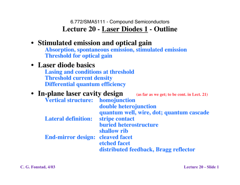
6.772/SMA5111 - Compound Semiconductors Lecture 20 - Laser Diodes 1 - Outline • Stimulated emission and optical gain Absorption, spontaneous emission, stimulated emission Threshold for optical gain • Laser diode basics Lasing and conditions at threshold Threshold current density Differential quantum efficiency • In-plane laser cavity design (as far as we get; to be cont. in Lect. 21) Vertical structure: homojunction double heterojunction quantum well, wire, dot; quantum cascade Lateral definition: stripe contact buried heterostructure shallow rib End-mirror design: cleaved facet etched facet distributed feedback, Bragg reflector C. G. Fonstad, 4/03 Lecture 20 - Slide 1 Laser diodes: comparing LEDs and laser diodes Light emitting diodes vs. Laser diodes LEDs are based on spontaneous emission, and have 1. 2. 3. 4. A broad output beam that is hard to capture and focus A relatively broad spectral profile Low to moderate overall efficiency Moderate to high speed (≈ 1/tmin) Laser Diodes are based on stimulated emission, and have the opposite characteristics 1. 2. 3. 4. Narrow, highly directed output Sharp, narrow emission spectrum High differential and overall efficiency High to very high speed Stimulated emission occurs when a passing photon triggers the recombination of an electron and hole, with emission of a second photon with the same frequency (energy), momentum, and phase. C. G. Fonstad, 4/03 Lecture 20 - Slide 2 Laser diodes: achieving stimulated gain To understand what is necessary to obtain net optical gain, rather than net absorption, we consider optical transitions between two levels in a solid (E1 and E2), and we look at three transitions ocurring with the absorption or emission of photons: 1. from E1 to E2 due to absorption 2. from E2 to E1 due to spontaneous emission 3. from E2 to E1 due to stimulated emission We model the rate of each process using the Einstein A and B coefficients, and then find when the probability is higher that a photon passing will stimulate emission than be absorbed. C. G. Fonstad, 4/03 Lecture 20 - Slide 3 Laser diodes: achieving stimulated gain, cont. In a semiconductor we consider one state, E1, to be in the valence band, and the other, E2 to be in the conduction band: E2 - - - Ec hn hn E1 hn + Absorption + Spontaneous emission hn + Ev Stimulated emission The rates these processes occur depend on the populations: Absorption rate, Rab: photon pop. x E1 pop. x E2 empty state pop. Spontaneous emission rate, Rsp: E2 pop. x E1 empty state pop. Stimulate emission rate, Rst: E2 pop. x E1 empty state pop. x photon pop. C. G. Fonstad, 4/03 Lecture 20 - Slide 4 Laser diodes: achieving stimulated gain, cont Absorption rate: Rab = B12 ⋅ f1 ⋅ N v (E1 ) ⋅ (1- f 2 ) ⋅ N c (E 2 ) ⋅ r p ( E 2 - E1 ) where B12: N v: N c: rp(E2-E1): fi: where transition probability for absorption valence band density of states at E1 conduction band density of states at E2 density of photons with correct energy Fermi function evaluated at Ei ( fi = 1 e E i -E fi ) +1 Efi: quasi-Fermi level for level i Spontaneous emission rate: Rsp = A21 ⋅ f 2 ⋅ N c (E 2 ) ⋅ (1- f1 ) ⋅ N v (E1 ) C. G. Fonstad, 4/03 Lecture 20 - Slide 5 Laser diodes: achieving stimulated gain, cont In the last equation we introduced: A21: transition probability for spontaneous emission Stimulated emission rate: Rst = B21 ⋅ f 2 ⋅ N c (E 2 ) ⋅ (1- f1 ) ⋅ N v (E1 ) ⋅ r p ( E 2 - E1) where B21: transition probability for stimulated emission Note, finally, that in these expressions the Fermi function is evaluated either in the conduction band (i = 2) or valence band (i =1): ( f1 = 1 e E1 -E fv ) +1 , ( f2 = 1 e E 2 -E fc ) +1 **************** The coefficients, A21, B12, and B21, are related, as we can see by looking at thermal equilibrium, where 8p ro3 2 1 Rab = Rsp + Rst , E fv = E fc , r p (E i ) = 3 3 E i E / kT hc (e -1) i C. G. Fonstad, 4/03 Lecture 20 - Slide 6 Laser diodes: achieving stimulated gain, cont Proceeding in this we we find: 8p ro3 E i2 B12 = B21, and A21 = B21 3 3 hc ************** Now we are ready to find the condition for optical gain, which we take as when the probability of stimulated emission is greater than that for absorption. Looking back at our equations, we find Rst > Rab leads to: B21 ⋅ f 2 N c ⋅ (1- f1 ) N v ⋅ r p ( E 2 - E1 ) > B12 ⋅ f1N v ⋅ (1- f 2 ) N c ⋅ r p ( E 2 - E1 ) Canceling equivalent terms yields: f 2 (1- f1 ) > f1 (1- f 2 ) and substituting the appropriate Fermi functions gives us: E fc - E fv > ( E 2 - E1 ) = hu ≥ E g C. G. Fonstad, 4/03 Lecture 20 - Slide 7 Laser diodes: achieving stimulated gain, cont. Our conclusion is that we will have net optical gain, i.e., more stimulated emission than absorption, when we have the quasi-Fermi levels separated by more than the band gap. This in turn requires high doping and current levels. It is the equivalent of population inversion in a semiconductor: E - E > E fc fv g ************** Next we relate the absorption coefficient, a, to Rab, Rst, and Rsp. A bit of thought shows us that we can say: Rab (E ) > [ Rst (E ) + Rsp (E )] ª Rst (E ) Æ a (E ) > 0 Net loss Net gain Rab (E ) < [ Rst (E ) + Rsp (E )] ª Rst (E ) Æ a (E ) < 0 Rab (E ) = [ Rst (E ) + Rsp (E )] ª Rst (E ) Æ a (E ) = 0 Æ E = E fc - E fv Notes: Spontaneous emission is negligible because it is randomly directed. It starts the lasing process, but it does not sustain it. The point at which a = 0 is called the transparency point. C. G. Fonstad, 4/03 Lecture 20 - Slide 8 Laser diodes: optical gain coefficient, g(E) The negative of the absorption coefficient is defined as the gain coefficient: g(E ) ≡ - a (E ) Writing the light intensity in terms of g(E) we have: L(E, x) = Lo (E )e-a ( E )x = Lo (E )e g( E )x ************** Stimulated recombination is proportional to the carrier populations, and in a semiconductor one carrier is usually in the minority and its population is the one that changes significantly with increasing current injection. If we assume p-type material, we have: g > 0 Æ n > n tr To first order, the gain will be proportional to this population, to the extent that it exceeds the transparency level: g @ G(n - n tr ) C. G. Fonstad, 4/03 Lecture 20 - Slide 9 Laser diodes: threshold current We not look at a laser diode and calculating the threshold current for lasing, and the light-current relationship Consider the following cavity: Lasing will be sustained when the optical gain exceeds the optical losses for a round-trip in the cavity. The threshold current is the current level above which this occurs. C. G. Fonstad, 4/03 Lecture 19 - Slide 18 Laser diodes: threshold current, cont. Track the light intensity on a full circuit, beginning with Io just inside the facet at x = 0+, and directed to the right: 1. 2. 3. 4. 5. At At At At At x x x x x = = = = = 0 + , directed to the right, I(0 + ) = Io L-, directed to the right, I(L- ) = Ioe( g-a l ) L L-, directed to the left, I(L- ) = R 2 Ioe( g -a l ) L 0 + , directed to the left, I(0 + ) = R2 Ioe( g -a l ) 2L 0 + , directed to the right, I(0 + ) = R1 R2 Ioe( g-a l ) 2L For sustained lasing we must have the intensity after a full circuit (5) be equal to, or greater than, the initial intensity (1): R1 R2 Ioe( g-a ) 2L ≥ Io l C. G. Fonstad, 4/03 Lecture 20 - Slide 11 Laser diodes: threshold current, cont. This leads us to identify the threshold gain, gth: 1 Ê 1 ˆ gth ≡ a l + ln Á ˜ 2L Ë R1 R2 ¯ To relate this threshold gain to current we recall that the gain is proportional to the carrier population in excess of the transparency value, g ª G( n - n tr ) = G'G( n - n tr ) where G': the portion of G due to material parameters alone G: the portion of G due to geometrical factors (i.e., the overlap of the optical mode and the active medium) and that the population will in general be proportional to the current: n ª KiD where K: a proportionality factor that depends on the device structure, which we will determine in specific situations later C. G. Fonstad, 4/03 Lecture 20 - Slide 12 Laser diodes: threshold current, cont. Writing g in terms of iD, and setting it equal to gth, yields: gth = G' G (KiD - n tr ) 1 Ê 1 ˆ = al + ln Á ˜ 2L Ë R1 R2 ¯ The diode current that corresponds to this threshold gain is defined to be the threshold current, Ith: 1 iD @gth ≡ Ith = K Ê 1 È ˆ 1 Ê 1 ˆ˘ ÁÁ ln Á Ía l + ˜˙ + n tr ˜˜ 2L Ë R1 R2 ¯˚ ¯ Ë G'G Î (This will take on more meaning as we look at specific laser diode geometries and quantify the various parameters.) ************* A final useful observation is that the mirror reflectivity term in these equations can be viewed as a mirror loss coefficient, am: 1 Ê 1 ˆ am ≡ ln Á ˜ 2L C. G. Fonstad, 4/03 Ë R1 R2 ¯ Lecture 20 - Slide 13 Laser diodes: threshold current, cont. Above threshold, essentially all of the additional excitation fuels stimulated recombination, and n' stays fixed at its threshold value. So too does Efn - Efp, which implies that the junction voltage is also pinned. The current-voltage and power-current characteristics of a laser diode thus have the following forms: iD Popt µ 1/Rseries µ hed Ith vAB current-voltage C. G. Fonstad, 4/03 Ith power-current iD Lecture 20 - Slide 14 Laser diodes: output power, Popt, and external differential quantum efficiency, hed To calculate the optical output power, Popt, we begin with several points: First, we recall that a particle flux can be written in terms of a particle density times their velocity. This holds for photons as well, and the velocity is the mode, or "group" velocity: Fph (x, y,z) = v g N ph ( x, y,z) Second, we recall that the rate of change of a photon population with time at a given point, is the photon flux times the absorption coefficient, a: ∂N ph (x, y, z) = - a v g N ph (x, y, z) ∂t Finally, we note that the output power will be the flux of photons emitted times the energy per photon, hn. Pout = hn Fph,out,tot C. G. Fonstad, 4/03 Lecture 20 - Slide 15 Laser diodes: Popt and hed, cont. We next move inside the laser diode and look at the photon population there. The total number of photons inside the laser will be N ph,in,tot = Ú N ph,in (x, y, z) dx dy dz This photon population is decreasing because photons are being absorbed internally and emitted from the ends of the cavity at a rate given by the photon flux times the effective absorption coefficient: Loss : Ú (a l + a m ) v g N ph,in (x, y, z) dx dy dz = (a l + a m ) v g N ph,in,tot Note that the loss out the end mirrors, am, is the output we are looking to calculate! and it is increasing because the diode current exceeds the threshold current, and the gain exceeds the threshhold gain: iD - I th ) ( Photon generation : Ú g v g N ph,in (x, y, z) dx dy dz = hi q C. G. Fonstad, 4/03 Lecture 20 - Slide 16 Laser diodes: Popt and hed, cont. In the last equation, hi, is the current utilization efficiency, the fraction feeding stimulated recombination. In the steady state the loss equals the generation: iD - I th ) ( hi (a l + a m ) v g N ph,in,tot = q Thus the total photon population inside the laser diode is: N ph,in,tot = (iD - I th ) h i q (a l + a m ) v g The total photon flux emitted from the laser diode output mirrors is the portion of the "loss" due to am: iD - I th ) am ( Popt = hn a m v g N ph,in,tot = hn hi q (a l + a m ) C. G. Fonstad, 4/03 Lecture 20 - Slide 17 Laser diodes: Popt and hed, cont. We next introduce the extraction efficiency, he: am he ≡ (a l + a m ) With this we write the output power as: iD - I th ) ( Popt = hn he hi q Note that this is the total output power from both ends of the laser. If the two end-faces have equal reflectivities, then half the power will come out each end. If one end is much more highly reflecting than the other, then little power will come out it, and all of the power will come out the lower reflectivity facet. If the reflectivities of the ends differ, but not by a large amount, then the division of output is complicated to calculate. Next we turn to the external differential quantum efficiency. C. G. Fonstad, 4/03 Lecture 20 - Slide 18 Laser diodes: Popt and hed, cont. The external differental quantum efficiency is defined as the ratio between the number of photons emitted per unit time, divided by the number of carriers crossing the diode junction per unit time: D ( # of photons out/unit time) hed = D (# of carriers across junction/unit time) In terms of the output power and diode current this is: hed = D (Popt / hn ) D (iD /q) q dPopt = hn diD Using the result on the previous foil, we find: hed = he hi C. G. Fonstad, 4/03 Lecture 20 - Slide 19 Laser diodes: device design and optimization With this general background, we now go to the white board and turn to looking at specific device design and the evolution of diode laser structures over time. • We will begin looking at evolution of active region design and the vertical device structure. • Next we turn to lateral definition of the cavity. • Finally we look at defining the ends of the cavity. • This initial discussion will focus on in-plane lasers. After this we will turn to vertical cavity devices. • At the very end we will discuss laser diode modulation. C. G. Fonstad, 4/03 Lecture 20 - Slide 20

