Document 10322756
advertisement

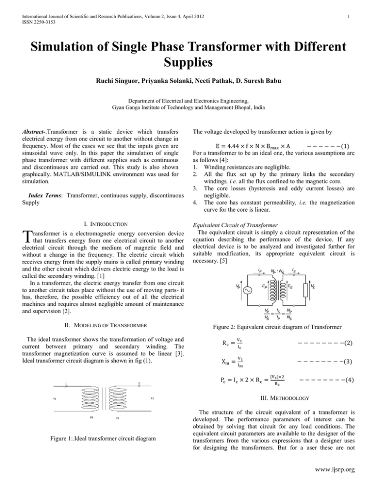
International Journal of Scientific and Research Publications, Volume 2, Issue 4, April 2012 ISSN 2250-3153 1 Simulation of Single Phase Transformer with Different Supplies Ruchi Singuor, Priyanka Solanki, Neeti Pathak, D. Suresh Babu Department of Electrical and Electronics Engineering, Gyan Ganga Institute of Technology and Management Bhopal, India Abstract-.Transformer is a static device which transfers electrical energy from one circuit to another without change in frequency. Most of the cases we see that the inputs given are sinusoidal wave only. In this paper the simulation of single phase transformer with different supplies such as continuous and discontinuous are carried out. This study is also shown graphically. MATLAB/SIMULINK environment was used for simulation. Index Terms: Transformer, continuous supply, discontinuous Supply I. INTRODUCTION T ransformer is a electromagnetic energy conversion device that transfers energy from one electrical circuit to another electrical circuit through the medium of magnetic field and without a change in the frequency. The electric circuit which receives energy from the supply mains is called primary winding and the other circuit which delivers electric energy to the load is called the secondary winding. [1] In a transformer, the electric energy transfer from one circuit to another circuit takes place without the use of moving parts- it has, therefore, the possible efficiency out of all the electrical machines and requires almost negligible amount of maintenance and supervision [2]. II. MODELING OF TRANSFORMER The voltage developed by transformer action is given by For a transformer to be an ideal one, the various assumptions are as follows [4]: 1. Winding resistances are negligible. 2. All the flux set up by the primary links the secondary windings, i.e. all the flux confined to the magnetic core. 3. The core losses (hysteresis and eddy current losses) are negligible. 4. The core has constant permeability, i.e. the magnetization curve for the core is linear. Equivalent Circuit of Transformer The equivalent circuit is simply a circuit representation of the equation describing the performance of the device. If any electrical device is to be analyzed and investigated further for suitable modification, its appropriate equivalent circuit is necessary. [5] Figure 2: Equivalent circuit diagram of Transformer The ideal transformer shows the transformation of voltage and current between primary and secondary winding. The transformer magnetization curve is assumed to be linear [3]. Ideal transformer circuit diagram is shown in fig (1). III. METHODOLOGY Figure 1:.Ideal transformer circuit diagram The structure of the circuit equivalent of a transformer is developed. The performance parameters of interest can be obtained by solving that circuit for any load conditions. The equivalent circuit parameters are available to the designer of the transformers from the various expressions that a designer uses for designing the transformers. But for a user these are not www.ijsrp.org International Journal of Scientific and Research Publications, Volume 2, Issue 4, April 2012 ISSN 2250-3153 available most of the times. In order to get the equivalent circuit parameters various test are conducted on transformer [6]. The various parameters of a transformer can be easily determined by two tests: I. Open-circuit test 2 magnitude of 229 volts. Similarly when 230volts square voltage waveform is applied as input to the transformer then the output voltage waveform is same as input voltage waveform having a voltage magnitude of 230volts as shown in Figure 3. These results are noticed to be as same as open circuit results. II. Short circuit test In this paper different type of supplies are given to the transformer namely: A. Continuous supply: Continuous supply can be defined as the supply where the current and the inductive energy storage never reaches zero. The various types of continuous supply are like:-Saw tooth, square, sinusoidal, triangular wave etc. [7] 1. Sinusoidal Waveform: The sine wave or sinusoid wave is a mathematical function that describes a smooth repetitive oscillation. It occurs often in pure mathematics, well as physics, signal processing, electrical engineering and many other fields.[9] ∑ ( Square Waveform: A square wave is a kind of nonsinusoidal waveform, most typically encountered in electronics and signal processing. An ideal square wave alternates regularly and instantaneously between two levels.[9] ∑( Open Circuit Test Table I: Simulation Results for Open Circuit with Continuous Sinusoidal and Square wave ) The above equation is valid for only n=2, 4, 6……and at n=1, 3, 5……. an=0. 2. Figure3: Wave Forms for (a) input voltage (b) input current (c) output voltage with Sinusoidal and Square ) The above equation is valid for only n=1, 3, 5……. and at n=2, 4, 6…… an=0. S. no Input Waveform Primary Current (A) Primary Voltage(V) Secondary Voltage(V) 1. Sine wave Square wave 0.40 230 229 0.08 230 230 2. Sinusoidal wave: During open circuit test when sinusoidal voltage waveform is applied to the transformer then the output voltage waveform is same as input voltage waveform having a voltage magnitude of 229volts as shown in Figure 4. B. Discontinuous supply: Discontinuous supply can be defined as the supply when the current and inductive energy storage may reach or cross zero. The various types of discontinuous supply are like: half sinusoidal wave, square pulse etc. [10] 1. Square Pulse: A pulse wave or pulse train is a kind of non-sinusoidal waveform that is similar to a square wave, but does not have the symmetrical shape associated with a perfect square wave.[8] III. CASE STUDY AND RESULTS CASE I: When the Single Phase Transformer was simulated with Continuous Supply with 230volts sinusoidal voltage waveform applied as input to the transformer then the output voltage waveform is same as input voltage waveform having a voltage Figure.4: Wave Forms for (a) input voltage (b) input current (c) output voltage with Sinusoidal Square wave: www.ijsrp.org International Journal of Scientific and Research Publications, Volume 2, Issue 4, April 2012 ISSN 2250-3153 3 As shown in Figure.5, during open circuit test when square voltage waveform is applied to the transformer then the output voltage waveform is slightly different from input voltage waveform having a voltage magnitude of 230volts. Figure.7: Wave Forms for (a) input voltage (b) input current (c) output voltage with Square Figure.5: Wave Forms for (a) input voltage (b) input current (c) output voltage with Square Short Circuit Test CASE II: Simulation of single phase transformer with Discontinuous supply Open Circuit Test Table II: Simulation Results for Short circuit with Continuous sinusoidal and square wave Table III: Simulation Results for Open circuit with Discontinuous sinusoidal and square wave S. no. Input waveform Primary Current(A) Primary Voltage(V) Secondary Current(A) S. no. Input waveform Primary Current(A) Primary Voltage(V) Secondary Voltage(V) 1. Sine wave 13 14 213.20 1. Sine Wave 0.78 229.8 229.6 2. Square wave 13 9 312.82 2. Square Wave 1.08 229.3 228.97 Sinusoidal wave: During short circuit test when sinusoidal voltage waveform is applied to the transformer then the output current waveform is same as input current waveform having a current magnitude of 213.20amp as shown in fig 6. Figure 6: Wave Forms for (a) input voltage (b) input current (c) output voltage With Sinusoidal and Square Square wave: During short circuit test when square voltage waveform is applied to the transformer then the output current waveform is slightly different from input current waveform as shown in figure.7 having a voltage magnitude of 312.82. Sinusoidal wave: From figure 8 open circuit test with sinusoidal voltage waveform of transformer is shown. The output voltage waveform is same as input voltage waveform having a voltage magnitude of 229.6volts. Figure 8: Wave Forms for (a) input voltage (b) input current (c) output voltage With Sinusoidal Square wave: During open circuit test when square voltage waveform is applied to the transformer then the output voltage waveform is same as input voltage waveform having a voltage magnitude of 228.97volts as shown in figure 9. www.ijsrp.org International Journal of Scientific and Research Publications, Volume 2, Issue 4, April 2012 ISSN 2250-3153 Figure 9: Wave Forms for (a) input voltage (b) input current (c) output voltage with Square 4 Figure 11: Wave Forms for (a) input voltage (b) input current (c) output voltage with Square IV. CONCLUSION Short Circuit Test Table IV: Simulation Results for Open circuit with Discontinuous sinusoidal and square wave S. no. Input waveform Primary Current(A) Primary Voltage(V) Secondary Current(A) 1. Sine Wave 13 12 278.98 2. Square Wave 13 8.5 408.4 Sinusoidal wave: During short circuit test when sinusoidal voltage waveform is applied to the transformer then the output current waveform is same as input current waveform having a current magnitude of 278.98amp as shown in figure 10. From simulation results it can be noted that when a transformer is operated with different types of supply then the output and input waveform are not same. It was also observed that the output voltage and current waveform is not in the same phase. Tests were performed by using continuous supplies as well as discontinuous supplies and graphs are plotted for different voltages and currents. It was also observed that voltage leads the current not exactly at 90degree but at some angle less than 90 degree. APPENDIX-A Specifications of transformer R1=0.2Ω, X1=0.5Ω, I1=13A, V1=230V, R2=0.2Ω, X2=0.5Ω, I2=13A, V2=230V, R0=718.7Ω, X0=958.3Ω, I0=0.4A, Ic=0.32A, Im=0.24A, L1=1.593* H, L2=1.593* H, L0=3.00H, Power factor= 0.8 ACKNOWLEDGMENT Authors are grateful to the management of Gyan Ganga Institute of Technology & Management, Bhopal & Dr.P.S.Venkataramu, Principal GGITM for his kind support during this work and Dr. Ravindranath C. Cherukuri, Director Research Incubation Centre & Head of Electrical department, GGITM for his constant encouragement during this work. REFERENCES Figure 10: Wave Forms for (a) input voltage (b) input current (c) output voltage with Sinusoidal Square wave: During short circuit test when square voltage waveform is applied to the transformer then the output current waveform is slightly different from input current waveform having a voltage magnitude of 408.4 as shown in figure 11. [1]. Dr. P. S. Bimbra, “Generalized Theory of Electrical Machines” Khanna publishers, Fifth Edition. [2]. D.P. Kothari & I.J. Nagrath, “Basic Electrical Engineering”, Tata McGraw hills publishers, Second Edition. [3]. J B Gupta, “Theory and performance of Electrical Machines”, S.K. Kataria and Sons publishers, Fourteen Edition. [4]. B.L. Theraja and A.K. Theraja, “A Textbook of Electrical Technology Vol II”, S. Chand publishers, Eighth Edition 2005. www.ijsrp.org International Journal of Scientific and Research Publications, Volume 2, Issue 4, April 2012 ISSN 2250-3153 [5]. Ronalad N. Bracewell, “The Fourier Transform And its Application”, Tata McGraw hills publishers, Third Edition. [6]. Ashfaq Hussain, “Electrical Machines”, CBS publishers, Fifth Edition. [7]. V. K. Mehta and Rohit Mehta, “Basic Electrical Engineering”, S .Chand publisher, Sixth Edition. [8]. A. E. Fitzegerald Charles Kingsley, Jr. Stephen D. Umans “Electrical Machinery”, Tata McGraw hills publishers, Sixth Edition. [9]. William H. Bartley P. E, “Analysis of Transformer Failures” IEEE-The Hartford Steam Boiler Inspection & Insurance Co Hartford, CT USA. [10]. M. Sedighizadeh and M. Khatibi, “An Approach for Accurate Designing of Transformers Supplying DC Load Currents” IEEE -International Journal of Computer and Electrical Engineering, Vol.2, No.6, December, 2010, 1793-8163. 5 AUTHORS Ruchi Singuor, Department of Electrical and Electronics Engg, Gyan Ganga Institute of Technology and Management, Bhopal, India Priyanka Solanki, Department of Electrical and Electronics Engg, Gyan Ganga Institute of Technology and Management, Bhopal, India, solankipriya1990@gmail.com Neeti Pathak, Department of Electrical and Electronics Engg, Gyan Ganga Institute of Technology and Management, Bhopal, India, neetipathak17@gmail.com D.Suresh Babu, Asst. Prof, Department of Electrical & Electronics Engg, Gyan Ganga Institute of Technology and Management, Bhopal, Madhya Pradesh, India sureshbabudaram@gmail.com www.ijsrp.org


