EE457M1_F98 - faraday - Eastern Mediterranean University
advertisement
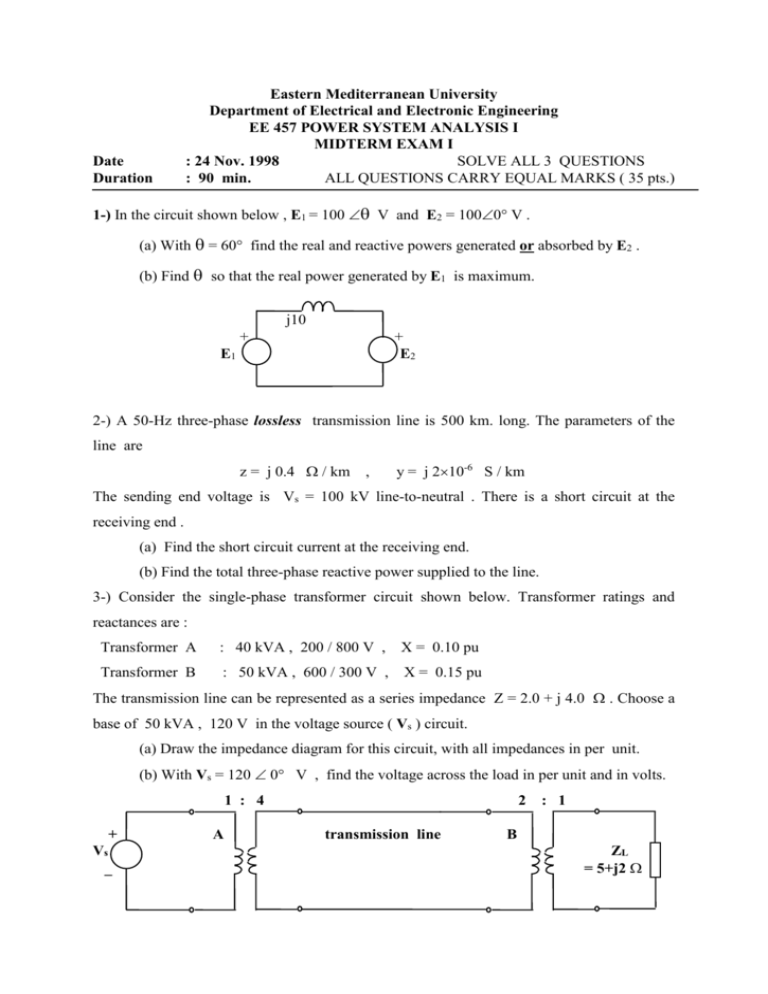
Date Duration Eastern Mediterranean University Department of Electrical and Electronic Engineering EE 457 POWER SYSTEM ANALYSIS I MIDTERM EXAM I : 24 Nov. 1998 SOLVE ALL 3 QUESTIONS : 90 min. ALL QUESTIONS CARRY EQUAL MARKS ( 35 pts.) 1-) In the circuit shown below , E1 = 100 V and E2 = 1000 V . (a) With = 60 find the real and reactive powers generated or absorbed by E2 . (b) Find so that the real power generated by E1 is maximum. j10 + + E2 E1 2-) A 50-Hz three-phase lossless transmission line is 500 km. long. The parameters of the line are z = j 0.4 / km , y = j 210-6 S / km The sending end voltage is Vs = 100 kV line-to-neutral . There is a short circuit at the receiving end . (a) Find the short circuit current at the receiving end. (b) Find the total three-phase reactive power supplied to the line. 3-) Consider the single-phase transformer circuit shown below. Transformer ratings and reactances are : Transformer A : 40 kVA , 200 / 800 V , X = 0.10 pu Transformer B : 50 kVA , 600 / 300 V , X = 0.15 pu The transmission line can be represented as a series impedance Z = 2.0 + j 4.0 . Choose a base of 50 kVA , 120 V in the voltage source ( Vs ) circuit. (a) Draw the impedance diagram for this circuit, with all impedances in per unit. (b) With Vs = 120 0 V , find the voltage across the load in per unit and in volts. 1 : 4 + Vs _ A 2 transmission line : 1 B ZL = 5+j2 Useful Information : 1.) Lossless transmission line equations V(x) = VR cos x + j Zc IR sin x j=zy I(x) = IR cos x + j ( VR / Zc ) sin x 2-) Change of per unit basis Sb Z pu Z pu S b 2 Vb 2 Vb Zc = z / y


