Force Analysis
advertisement
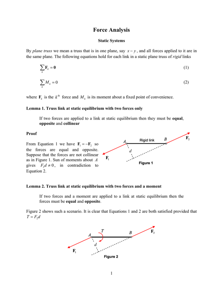
Force Analysis Static Systems By plane truss we mean a truss that is in one plane, say x y , and all forces applied to it are in the same plane. The following equations hold for each link in a static plane truss of rigid links F k 0 (1) k M k 0 (2) k where Fk is the k th force and M k is its moment about a fixed point of convenience. Lemma 1. Truss link at static equilibrium with two forces only If two forces are applied to a link at static equilibrium then they must be equal, opposite and collinear Proof Rigid link A From Equation 1 we have F1 F2 so the forces are equal and opposite. Suppose that the forces are not collinear as in Figure 1. Sun of moments about A gives F2 d 0 , in contradiction to Equation 2. B F2 d F1 Figure 1 Lemma 2. Truss link at static equilibrium with two forces and a moment If two forces and a moment are applied to a link at static equilibrium then the forces must be equal and opposite. Figure 2 shows such a scenario. It is clear that Equations 1 and 2 are both satisfied provided that T F2 d T B A d F1 Figure 2 1 F2 Lemma 3. A Three-Force Link If three forces are applied to a link at static equilibrium then they must close a triangle and their lines of action must pass through a common point. Proof The graphical interpretation of Equation 1 is that the three forces close a triangle, as in Figure 3b. Suppose that the forces from Figure 3b are applied on the link as in Figure 3a. Note that the lines of action for these forces do not pass through a common point. Sum of moments about A gives F2 d 0 , in contradiction to Equation 2. F1 F1 F2 F3 A d F2 F3 Figure 3a Figure 3b The link shown in Figure 4a is in static equilibrium. The three forces acting on it close the triangle shown in Figure 4b, and in addition the three lines of action of the forces pass through the common point A , shown in Figure 4a. F1 F2 F2 A F1 F3 F3 Figure 4a Figure 4b Definition: Fij is the force that link i applies on link j By Newton’s third law Fij F ji (3) 2 Example 1 P Given force P in the truss of Figure 5. Find the pin forces F12 , F32 , F23 , F13 . 2 3 Figure 5 Solution Link 2 is a two-force link. Therefore F13 and F23 are collinear, as shown in Figure 6b. By Newton’s third law F23 and F32 are equal and opposite. Hence, knowing P and the direction of F32 determines the direction of F12 , as in Figure 6a, since link 2 is a three-force link the lines of action must pass through a common point. The force triangle equilibrium shown in Figure 6c determines all pin forces of the truss which are shown in Figure 7. F32 F23 P F32 F12 3 2 P F12 F13 Figure 6a Figure 6b Figure 6c F32 F23 P 3 2 F12 F13 Figure 7a Figure 7b 3 Example 2 Given P and Q as shown in the figure below. Find the pin forces. Solution The problem is first broken into two sub-problems, ' and ' ' as shown. Each sub-problem is of the kind of two-force link and three-force link which can be solved as in Example 1. After solving the two problems, force superposition gives the pin forces F12 , F32 , F23 and F13 . This process is illustrated below. Q P 2 3 The problem Q P 2 Problem superposition 3 2 Problem (‘) F32 3 Problem (‘’) F23 F32 F23 P 3 2 Q 3 2 Solution to Problem (‘) Solution to Problem (‘’) F13 F12 F12 F13 Force superposition F12 F12 F32 F12 F32 F12 F12 F12 F32 F32 F32 F13 F23 F32 F23 F23 F23 F23 F23 4 F13 F13 F13 F13 F13 Dynamic systems For each link in a mechanism in motion the following equations hold: F k maG (4) I G (5) k M k k Where aG in the acceleration of the center of gravity G , I G is the moment of inertia about G , m is the mass of the link, and M k is the moment of the force Fk about G . D'Alembert's principle Define an inertia force as FI maG (6) and inertia moment as M I I G . (7) Then the dynamics equations (4) and (5) takes the statics equations form FI Fk 0 (8) MI Mk 0 . (9) k k The implication of the principle is that if we add the inertia forces and moments to the mechanism the force analysis may be done by using the statics methodology that was described above. 5 Stopping a link from accelerating Suppose that two forces FA and FB are acting on link AB with mass m and moment of inertia I G about the center of gravity G , as shown in the figure. As a result the link accelerates. The acceleration of G is aG and the angular acceleration of the link is , as show the figure. FI m maa G FB B FB FA G aG A FA Should the inertia force FI , expressed by equation 6, and shown in the figure, be applied to the link then the acceleration of G would vanish. If in addition the inertia force would be placed in a distance e such that e I G FI as shown it the figure below, then the inertia force FI would also cancel the angular acceleration of the link. Note that the moment applied by FI about G should be in an opposite sense to , i.e., if has CCW sense, as in the figure above, then the moment of FI about G should be with a CW sense, as in the figure below. FB B G e I G FI FI ma G A FA 6
