Otto Cycle Modeling
advertisement
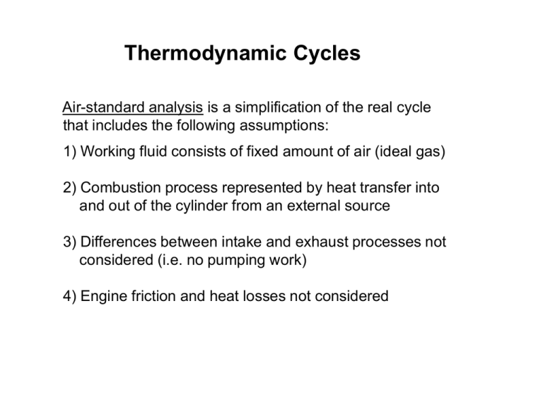
Thermodynamic Cycles Air-standard analysis is a simplification of the real cycle that includes the following assumptions: 1) Working fluid consists of fixed amount of air (ideal gas) 2) Combustion process represented by heat transfer into and out of the cylinder from an external source 3) Differences between intake and exhaust processes not considered (i.e. no pumping work) 4) Engine friction and heat losses not considered SI Engine Cycle vs Air Standard Otto Cycle FUEL A Ignition I R Fuel/Air Mixture Combustion Products Actual Cycle Intake Stroke Compression Stroke Power Stroke Qin Otto Cycle Air Exhaust Stroke Qout TC BC Compression Process Const volume heat addition Process Expansion Process Const volume heat rejection Process Air-Standard Otto cycle Process 1 2 Process 2 3 Process 3 4 Process 4 1 Isentropic compression Constant volume heat addition Isentropic expansion Constant volume heat rejection Compression ratio: v1 v4 r v2 v3 Qin Qout v2 TC v1 BC TC BC First Law Analysis of Otto Cycle 12 Isentropic Compression AIR Win Q (u 2 u1 ) ( ) m m Win (u 2 u1 ) m vr2 v2 1 vr1 v1 r P2 v2 P1v1 P2 T2 v1 R T2 T1 P1 T1 v2 First Law Analysis of Otto Cycle 23 Constant Volume Heat Addition Qin W (u3 u 2 ) ( ) m m Qin (u3 u 2 ) m P3 P3 T3 P2 v RT2 RT3 P2 T2 Qin AIR TC First Law Analysis of Otto Cycle 3 4 Isentropic Expansion Wout Q (u 4 u3 ) ( ) m m AIR Wout (u3 u 4 ) m vr4 v4 r vr3 v3 P4 v4 P3v3 P4 T4 v3 T4 T3 P3 T3 v4 First Law Analysis of Otto Cycle 4 1 Constant Volume Heat Removal Qout W (u1 u 4 ) ( ) m m Qout (u 4 u1 ) m P4 P1 P4 P1 v RT4 RT1 T4 T1 AIR Qout BC First Law Analysis Net cycle work: Wcycle Wout Win mu3 u4 mu2 u1 Cycle thermal efficiency: th th Wcycle Qin Wout Win u3 u4 u2 u1 u3 u2 Qin u3 u2 u4 u1 u3 u2 1 u4 u1 u3 u2 Cold Air-Standard Analysis • For a cold air-standard analysis the specific heats are assumed to be constant evaluated at ambient temperature values (k = cp/cv = 1.4). • For the two isentropic processes in the cycle, assuming ideal gas with constant specific heat using Pv k const. Pv RT yields: 12: 34: T2 v1 T1 v2 T4 v3 T3 v4 th const cV k 1 k 1 1 r k 1 1 r k 1 k 1 k T2 P2 T1 P1 k 1 k T4 P4 T3 P3 cv (T4 T1 ) T 1 1 1 1 k 1 cv (T3 T2 ) T2 r Effect of Specific Heat Ratio th const cV 1 1 r k 1 Specific heat ratio (k) Cylinder temperatures vary between 20K and 2000K where 1.2 < k < 1.4
