Status of the Tune and Orbit Measurements and - Indico
advertisement

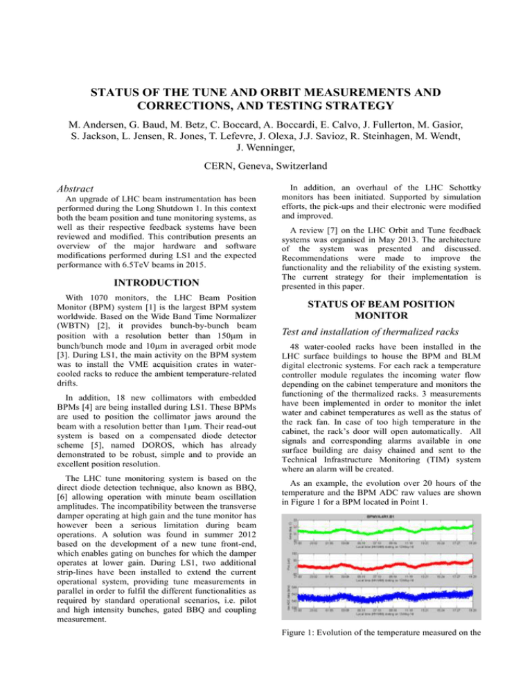
STATUS OF THE TUNE AND ORBIT MEASUREMENTS AND CORRECTIONS, AND TESTING STRATEGY M. Andersen, G. Baud, M. Betz, C. Boccard, A. Boccardi, E. Calvo, J. Fullerton, M. Gasior, S. Jackson, L. Jensen, R. Jones, T. Lefevre, J. Olexa, J.J. Savioz, R. Steinhagen, M. Wendt, J. Wenninger, CERN, Geneva, Switzerland Abstract An upgrade of LHC beam instrumentation has been performed during the Long Shutdown 1. In this context both the beam position and tune monitoring systems, as well as their respective feedback systems have been reviewed and modified. This contribution presents an overview of the major hardware and software modifications performed during LS1 and the expected performance with 6.5TeV beams in 2015. INTRODUCTION With 1070 monitors, the LHC Beam Position Monitor (BPM) system [1] is the largest BPM system worldwide. Based on the Wide Band Time Normalizer (WBTN) [2], it provides bunch-by-bunch beam position with a resolution better than 150m in bunch/bunch mode and 10m in averaged orbit mode [3]. During LS1, the main activity on the BPM system was to install the VME acquisition crates in watercooled racks to reduce the ambient temperature-related drifts. In addition, 18 new collimators with embedded BPMs [4] are being installed during LS1. These BPMs are used to position the collimator jaws around the beam with a resolution better than 1m. Their read-out system is based on a compensated diode detector scheme [5], named DOROS, which has already demonstrated to be robust, simple and to provide an excellent position resolution. The LHC tune monitoring system is based on the direct diode detection technique, also known as BBQ, [6] allowing operation with minute beam oscillation amplitudes. The incompatibility between the transverse damper operating at high gain and the tune monitor has however been a serious limitation during beam operations. A solution was found in summer 2012 based on the development of a new tune front-end, which enables gating on bunches for which the damper operates at lower gain. During LS1, two additional strip-lines have been installed to extend the current operational system, providing tune measurements in parallel in order to fulfil the different functionalities as required by standard operational scenarios, i.e. pilot and high intensity bunches, gated BBQ and coupling measurement. In addition, an overhaul of the LHC Schottky monitors has been initiated. Supported by simulation efforts, the pick-ups and their electronic were modified and improved. A review [7] on the LHC Orbit and Tune feedback systems was organised in May 2013. The architecture of the system was presented and discussed. Recommendations were made to improve the functionality and the reliability of the existing system. The current strategy for their implementation is presented in this paper. STATUS OF BEAM POSITION MONITOR Test and installation of thermalized racks 48 water-cooled racks have been installed in the LHC surface buildings to house the BPM and BLM digital electronic systems. For each rack a temperature controller module regulates the incoming water flow depending on the cabinet temperature and monitors the functioning of the thermalized racks. 3 measurements have been implemented in order to monitor the inlet water and cabinet temperatures as well as the status of the rack fan. In case of too high temperature in the cabinet, the rack’s door will open automatically. All signals and corresponding alarms available in one surface building are daisy chained and sent to the Technical Infrastructure Monitoring (TIM) system where an alarm will be created. As an example, the evolution over 20 hours of the temperature and the BPM ADC raw values are shown in Figure 1 for a BPM located in Point 1. Figure 1: Evolution of the temperature measured on the DAQ (green/top) and the beam position measured in m (red/middle) and in ADC bins (blue/bottom) for BPMYA.4R1.B1 The temperature variations were seen to be kept within 1°C peak to peak over 22h. The BPM reading using a calibration signal is still linearly correlated to the temperature however, using a correction algorithm; the RMS noise on the BPM reading is measured to be smaller than 5m. At this level, the noise could also be linked to the stability of the calibration source. More investigations are required to better understand the limitations of the upgraded system. Hardware and Software modifications Two new button-type BPMs were installed in Point 4 close to the BGI monitors and several BPMs were modified and repaired. For example the strip-lines BPM for ALFA, initially short-circuited, have been modified and are now terminated with 50Ohms loads. This will reduce the signal reflections in the system and improve the dynamic range. A survey campaign was also conducted on a few BPMs, which were marked by operation with possibly large mechanical offsets, e.g. BPMD. It turned out that BPMs at Q1 locations could only be aligned with an accuracy of ±1mm due to difficulties in accessing the BPM detector and visualising its survey target. system through an Ethernet link using UDP frames. DOROS is using a standalone architecture that fits in a standard 19” rack. Each box will process 8 orbit and 4 oscillation channels that could monitor either 2 collimators equipped with 4 buttons each or 2 regular BPMs having 4-electrodes. DOROS will be deployed on 18 TCTPs and TCSPs collimators currently installed on LHC during LS1. Providing a closed-orbit BPM resolution considerably better than the default LHC BPM system, DOROS will also be deployed on several BPMs in parallel to the existing system. All Q1 BPMs in point 1, 2, 5 and 8 will be equipped with DOROS in order to provide the best position resolution close to the LHC experiment. In addition 4 striplines on Q7 quadrupoles in point 7 will be equipped with DOROS to allow better coupling measurements. This is also the case for the BPMs used by the TOTEM experiments. TUNE MONITOR Two additional strip-line pick-ups have been installed during LS1 to complement the Tune monitoring system, as presented on Figure 3. In the BPM VME crates, all CPUs are being upgraded to MEN A20. The BPM FESA class is also being upgraded in order to correct for the BPM geometrical non-linearity using a new 2-D polynomial fit calibration, which includes x-y cross-terms [8]. Orbit measurement with diode detector The final version of the diode orbit system, DOROS [9], is presently under development. A sketch of the present system is shown on Figure 2. Figure 3: Layout of the LHC Tune Monitoring System The new features are highlighted in red in Figure 3. - - FFT2 and FFT3 are using gated BBQ (GBBQ) and standard BBQ electronic systems respectively. They provide the continuous tune and coupling measurements that are currently used by the feedback system. As the standard BBQ system observes all bunches, the gated BBQ electronic allows to measure just the selected bunches for which the transverse damper operates at a reduced gain. - DEV is a development tune system kept for beam studies. The Beam Transfer Function (BTF) measurements will be implemented as an MD tool first on the DEV system. Figure 2: Architecture of the LHC DOROS electronic: LPF: Low Pass Filter, PGA: Programmable Gain Amplifier, F: Follower, DA: Differential Amplifier, MC: Main Controller, SC: Synchronisation Circuitry, EPL: Ethernet Physical Layer DOROS includes a high-resolution (1m) beam orbit measurement system based on compensated diode detectors (CDD) as well as a beam oscillation measurement using diode peak detector (DPD). The latter can be seen as an evolution of the electronic originally developed for the tune measurement system. The system processes beam signals using a 24-bit analogue to digital converter. The orbit data is locally processed in an FPGA (MC) and sent out to the control FFT1 is the on-demand system typically used to perform measurements requiring changes in acquisition settings and/or beam excitation as needed for chromaticity measurements. Some operational software development is required to exploit the full functionality of standard and gated BBQs, with a GUI for bunch selection and bunch scans display. Status of Schottky monitor During the LHC Run 1, the LHC Schottky monitors [10] were able to provide high-level Schottky signals of good quality during all ion fills, for B1H, B1V and B2H, providing reliable single bunch measurements for the tune [11]. However, with protons only the B1H Schottky system gave acceptable Schottky signals, the signals of the other systems were below the noise floor. During LS1, the Schottky pick-ups have been modified and, basically, four new pick-ups have been designed, manufactured and assembled as depicted on Figure 4. New waveguides and beam pipe bars made out of copper instead of aluminium were produced to keep any possible thermal expansion matched to the slotted CuBe coupling foils. This will avoid the warping of the foils during bake-out cycles, which was observed on the previous design when the monitors were dismounted. Canted coil-springs are now implemented to guarantee a good RF contact between all parts of this sandwich construction. Figure 4: Picture of the new Schottky pick-up made out of copper bars and slotted CuBe foils. A new coaxial-to-waveguide launcher was designed using CST microwave studio. In order to minimise reflections and standing waves, its return-loss was improved over a frequency range from 4.6 to 5.0GHz frequency range. The RF front-end electronics will also be modified before the LHC restart. The current system, based on consecutive down-mixing stages, will be modified to operate with a tuneable input frequency in the 4.65.0GHz range. This will allow locating the optimal frequency, for which coherent signals are minimised. It requires a tuneable local oscillator for the first downmixing stage and a tuneable narrow-band input filter (YIG). In addition, a fast, high isolation gate switch will be implemented in front of the first amplifiers to improve the S/N for gated bunch operation. Remote control for all RF attenuators and phase shifters will also be implemented for increased flexibility. STATUS OF FEEDBACK SYSTEMS Both hardware and software modifications and improvements are currently implemented on the LHC feedback system. The machines running the Orbit Feedback Controller (OFC) and the Orbit Feedback Service Unit (OFSU) have been upgraded to new Gen8 computers. They can run up to 24 threads in parallel with 32GB memory. This has to be compared with the previous G5s machines limited to 4 threads and 12GB. The system is now composed of 4 identical units, 2 being the operational ones and 2 for development work. While the existing pre-LS1 will be kept as backup, the base-line means starting with newly implemented software described below for the feedback and serviceunit. This has implications for operational applications that will require modifications. Regular meetings with OP will allow detailing these changes and agree on short and medium-term milestones. Additional beam position data from collimator BPMs and normal pick-ups based on the DOROS electronics will be integrated in parallel to the standard LHC BPM acquisition system allowing the steering program to visualize them however it is presently not foreseen to close the feedback based on the data. The OFC will run in 64bit mode. The introduction of a standard timing module to the server will make the OFSU less critical to operation as it was now required to update the beam energy regularly. The splitting of the OFSU into 2 different FESA servers will be studied to facilitate the maintenance. One server will be dedicated to the OFSU proxy providing orbit and tune data to the control system while the second will handle the beam optic calculation and settings management. With the aim to suppress the ‘private’ Ethernet link between OFC and OFSU, the possibility to run them on the same machine will be studied exploiting the increase in thread performance. The deployment of new software versions needs to be looked into carefully. Changes and upgrades on the OFC may be done without any impact on beam operation during technical stops or ‘quiet’ periods. Modifications to the OFSU may be more critical with possibly some functionalities unavailable during a certain time. CONCLUSIONS AND PERSPECTIVES The installation of water-cooled racks performed during LS1 aims at an improved stability and reproducibility of the orbit BPM reading (<10um) over long time period. The use of the synchronous orbit for common beam-pipe BPMs should be tested and deployed operationally in order to limit the cross-talk between the two beams and to improve the accuracy of the position measurements at these locations. The implementation of a better correction of BPM geometrical non-linearity should also provide more accurate measurements. The new DOROS high-resolution orbit measurement system is being installed on 18 collimator BPMs as well on the 16 BPMs located close to Q1. It is expected to provide a better control of the beam position to optimise collision at IPs and integrated luminosity. The tune measurement system has two additional pick-ups to fully deploy the gated BBQ operationally and provide better coupling measurements. The measurement of the Beam Transfer Function (BTF) will be made operational responding to a direct request from MD users. A complete overhaul of the LHC Schottky monitors is currently being performed, with new pickups and electronics. It is expected to provide bunch-bybunch tune measurements and chromaticity measurements at injection and flat top energy. The architecture of the orbit and tune feedback system has been reviewed during LS1. Its computing capability has been increased considerably with more powerful machines and many software modifications have been launched aiming for better reliability in agreement with OP-LHC. REFERENCES [1] E. Calvo et al, “The LHC Orbit and Trajectory System”, Proceeding of DIPAC, Mainz, Germany, 2003, 187 [2] D. Cocq, “The Wide Band Normaliser: a New Circuit to Measure Transverse Bunch Position in Accelerators and Colliders”, Nucl. Instrum. Methods Phys. Res. A 416, 1998, 1. [3] E. Calvo et al, “The LHC Beam Position System: Performance during 2010 and Outlook for 2011”, Proceeding of DIPAC, Hamburg, Germany, 2011, 323 [4] A. Nosych et al, “Electromagnetic Simulations of an Embedded BPM in Collimator Jaws”, Proceeding of DIPAC, Hamburg, Germany, 2011, 71 [5] M. Gasior, J. Olexa, R.J. Steinhagen, "BPM electronics based on compensated diode detectors results from development systems", CERN-ATS-2012247. Proceeding of BIW, Newport News, Virginia, USA, 2012. [6] M. Gasior, "Faraday cup award: High sensitivity tune measurement using direct diode detection", CERN-ATS-2012-246. Proceeding of BIW, Newport News, Virginia, USA, 2012. [7] https://indico.cern.ch/event/241299/timetable/#201305 07 [8] A. Nosych et al, “LHC BPM non linearity corrections”, EDMS [9] M. Gasior, J. Olexa, R.J. Steinhagen, "BPM electronics based on compensated diode detectors results from development systems", CERN-ATS-2012- 247. Proceeding of BIW, Newport News, Virginia, USA, 2012. [10] F. Caspers et al, “The 4.8GHz LHC Schottky pick-up system”, Proceeding of the PAC Conference, Albuquerque, NM, USA, (2007) pp.4174 [11] M. Favier, et al, « Capabilities and Performance of the LHC Schottky Monitors », Proceeding of the DIPAC Conference, Hamburg, Germany, (2011) pp.44


