module aims, assessment and support
advertisement
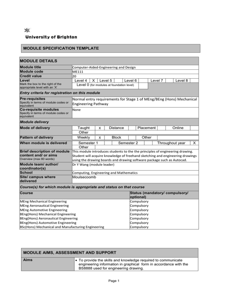
MODULE SPECIFICATION TEMPLATE MODULE DETAILS Module title Module code Credit value Level Mark the box to the right of the appropriate level with an ‘X’ Computer-Aided-Engineering and Design ME111 20 Level 4 X Level 5 Level 6 Level 0 (for modules at foundation level) Level 7 Level 8 Entry criteria for registration on this module Pre-requisites Specify in terms of module codes or equivalent Normal entry requirements for Stage 1 of MEng/BEng (Hons) Mechanical Engineering Pathway Co-requisite modules None Specify in terms of module codes or equivalent Module delivery Mode of delivery Pattern of delivery Taught Other Weekly X Distance Placement X Block Other Online When module is delivered Semester 1 Semester 2 Throughout year X Other Brief description of module This module introduces students to the the principles of engineering drawing. content and/ or aims Student will acquire knowledge of freehand sketching and engineering drawings Overview (max 80 words) using the drawing boards and drawing software package such as Autocad. Module team/ author/ Dr Y Wang (module leader) coordinator(s) School Computing, Engineering and Mathematics Site/ campus where Moulsecoomb delivered Course(s) for which module is appropriate and status on that course Course Status (mandatory/ compulsory/ optional) Compulsory Compulsory Compulsory Compulsory Compulsory Compulsory Compulsory MEng Mechanical Engineering MEng Aeronautical Engineering MEng Automotive Engineering BEng(Hons) Mechanical Engineering BEng(Hons) Aeronautical Engineering BEng(Hons) Automotive Engineering BSc(Hons) Mechanical and Manufacturing Engineering MODULE AIMS, ASSESSMENT AND SUPPORT Aims To provide the skills and knowledge required to communicate engineering information in graphical form in accordance with the BS8888 used for engineering drawing. Page 1 To develop the students’ mechanical design skills through practical and realistic case study. Learning outcomes Content On successful completion of this module the students will be able to: LO1 sketch concept designs. LO2 interpret and prepare engineering drawings as a means of communication for production of assemblies and detail of manufacture of components. LO3 produce two dimensional engineering drawings to BS8888 on a CAD package such as Autocad. LO4 use appropriate formulae for selection and design of machine elements for given engineering applications. Learning support Drawing standards and codes of practice: BS8888 Drawing types: differences between general arrangement, assembly and detail drawings. Layout: paper sizes, borders, title block, parts list. Projection systems: first and third angle projection, projection symbols. Lines and linework: line types and applications, thickness, leader lines and arrow heads. Lettering and symbols: style, height, direction and location. Common symbols (e.g. welding, machining) and abbreviations. Fits and tolerances: fits and tolerances for holes and shafts. Views: partial, sections and rules associated with hatching. Principles of dimensioning: projection and dimension lines, dimensioning methods, tolerance dimensions. Conventional representation: screw threads, gears, bearings, and springs. Design and selection of machine tool elements: Some of the following elements will be covered - gears, bearings, fasteners, shafts, belt and chain drives, clutches and brakes. The application of available 2D drawing package (Autocad) to the solution of real engineering problems. Indicative readings The most recent editions of: YARWOOD, A., Engineering drawing, Cassell. PHELPS, NEIL; SIMMONS, COLIN H., Engineering drawing practice: a guide for further and higher education to BS 8888:2006, Technical product specification (TPS), BSI. SIMMONS, COLIN H., Manual of engineering drawing, ButterworthHeinemann. JENSEN, CECIL; HELSEL, JAY D., Engineering drawing and design, McGraw-Hill. ONSTOTT, SCOTT., AutoCAD 2015 and AutoCAD LT 2015 essentials, Autodesk Official Press. FINKELSTEIN, ELLEN., AutoCAD 2013 and AutoCAD LT 2013 bible, John Wiley. TICKOO, SHAM., AutoCAD 2012: a problem-solving approach, Cengage Learning. HAMAD, MUNIR M., AutoCAD 2014: beginning and intermediate, Mercury Learning and Information. SHROCK, CHERYL R., Beginning AutoCAD 2015: exercise workbook, Industrial Press Inc. FANE, BILL., Autocad® 2014 for dummies®, Hoboken, NJ. YARWOOD, A., Introduction to AutoCAD 2013, Routledge. BETHUNE, JAMES D., Engineering graphics with AutoCAD 2015, Peachpit Press. Online sources Page 2 A number of relevant and up-to-date web resources will be identified during module delivery. Software The main package used will be AutoCAD Teaching and learning activities Details of teaching and learning activities Teaching will take the form of three hours per week to include demonstrations, and opportunities for computer lab work. Mainly hands on practical sessions complemented by some formal instructions to cover basic principles. Some of module’s delivery time will be devoted to the use of 2D CAD systems. Learning will be developed from basic instructions on how to use the 2D software to a point where students can undertake a series of exercises by themselves. Lectures to teach fundamental principles of engineering drawings will be given. Presentations, demonstrations and examples of good practice taken from industrial applications will be given. Students will be expected to spend about five hours per week studying the principles of engineering drawing, practicing computer-based techniques and engaging with coursework/revision. Allocation of study hours (indicative) Study hours Where 10 credits = 100 learning hours SCHEDULED This is an indication of the number of hours students can expect to spend in scheduled teaching activities including lectures, seminars, tutorials, project supervision, demonstrations, practical classes and workshops, supervised time in workshops/ studios, fieldwork, external visits, and work-based learning. 78 GUIDED INDEPENDENT STUDY All students are expected to undertake guided independent study which includes wider reading/ practice, follow-up work, the completion of assessment tasks, and revisions. 122 PLACEMENT The placement is a specific type of learning away from the University that is not work-based learning or a year abroad. N/A TOTAL STUDY HOURS 200 Assessment tasks Details of assessment for this module There are THREE assessment elements. The first two are in-class practical skills tests using drawing boards and AutoCAD covering LO1, LO2, LO3. The second is a design project covering LO1, LO2, LO3 and LO4. Types of assessment task1 % weighting Indicative list of summative assessment tasks which lead to the award of credit or which are required for progression. (or indicate if component is pass/fail) WRITTEN 30% In-class drawing board test (30%) 1 Set exercises, which assess the application of knowledge or analytical, problem-solving or evaluative skills, are included under the type of assessment most appropriate to the particular task. Page 3 COURSEWORK In-class AutoCAD test 2 (30%) 30% Design project (40%) 40% PRACTICAL 0% EXAMINATION INFORMATION Area examination board Engineering and Product Design Refer to Faculty Office for guidance in completing the following sections External examiners Name Position and institution Date appointed Date tenure ends Dr S Brookes Manchester Metropplitan University October 2012 September 2016 Yes No QUALITY ASSURANCE Date of first approval 02/01/2005 Only complete where this is not the first version Date of last revision 06/01/2010 Only complete where this is not the first version Date of approval for this version Version number 14/10/15 Modules replaced None Specify codes of modules for which this is a replacement Available as free-standing module? Page 4 X

