Strain notes Mar 6
advertisement
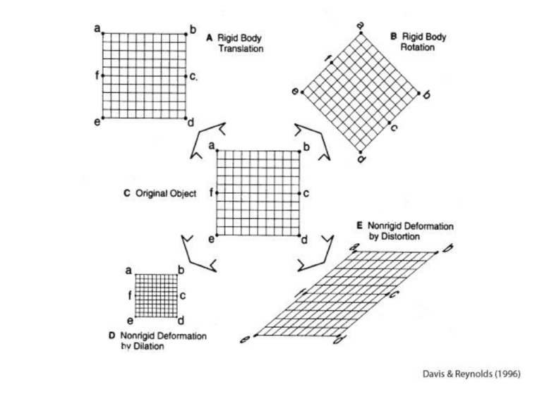
xx xy 0.1 0 ij 0.2 yx yy 0 y (0,11) (9,12) (0,10) (10,10) (9,0) (10,0) X xx yy 0.1 0.2 0.1 This is the trace of the strain tensor. In general the trace of the strain tensor gives area change in 2-D and volume change in 3-D The principal axes are directions along which the starting vector and ending vector are parallel Pure shear = principal axes do not rotate with time Principal Axes 1 2 3 = maximum stretch direction Intermediate stretch direction Minimum stretch direction (or most contractional) The principal axes are all mutually orthogonal to one another xx xy 0.1 0.1 ij yx yy 0.1 0.1 x 0.1x 0.1y y 0.1x 0.1y (10 ,0)becomes (11,1) (10,-10) remains fixed, as does (-10, 10) (0, 10) becomes (1,11) (10,10) becomes (12,12) etc... y (12,12) (1,11) (10,10) (0,10) (11,1) (10,0) X In principal axis coordinate system this tensor can be written: xx xy 0.2 0.0 ij yx yy 0.0 0.0 Simple Shear • In Simple shear the principal axes rotate with increasing shear • Simple shear applies only to finite strain Rotational strain Marker This part of marker not disformed Stress = Force/Area Force is measured in units of mass*acceleration 1 N (Newton) = 1 kg * m * s-2 another common unit for force is the pound Pressure is a number. It corresponds to a special kind of stress. Stress is a tensor, but it has the same units as pressure (Pa) 1000 Pa = 1 kPa 1,000,000 Pa = 1 MPa (about 10 bars) Traction is a Vector • Tractions are vectors = force/area • Traction can be resolved into two components Normal component to plane = normal stress Tangential component = shear stress The stress tensor • • • • The stress tensor is symmetric The stress tensor has 3 principal axes The principal axes are mutually orthogonal principal axis = direction in which the traction vector is parallel to normal to plane => no shear stress resolved on that plane 1 = maximum compressive principal stress 2 = intermediate compressive principal stress 3 = minimum compressive principal stress Normal Stress and Shear Stress n = Normal Stress resolved on plane = shear stress resolved on plane Anderson Faulting Theory • If 1 is vertical then a new fault will be a normal fault (extensional) • If 1 is horizontal and 3 is vertical then reverse (thrust) fault (contractional faulting) • If 1 and 3 are both horizontal then strikeslip (transcurrent) fault Fault Angles and Principal Stresses 2 in the plane of the fault 1 20°-40° from the plane of the fault 3 50°-70° from the plane of the fault 3 1 1 3 n = (1+3)/2 - [(1-3)/2] cos 2 = [(1-3)/2] sin 2 THESE ARE ALSO THE EQUATIONS FOR A CIRCLE WITH A RADIUS OF (1-3)/2 AND A CENTER (1+3)/2 TO THE RIGHT OF WHERE THE AXES CROSS!!!! pe o l ve n e d el i y al n o i t c i fr = atan n fric tion al yie ld e nve lop e 3 1 3 1 n Let’s Look at internal friction angles, coefficients of friction, and theta • If =10° (so =tan=0.18), then 2=80°, so =40° and 1 axis is 40° from the fault plane. • If =20° (so =tan=0.36), then 2=70°, so =35° and 1 axis is 35° from the fault plane. • If =30° (so =tan=0.58), then 2=60°, so =30° and 1 axis is 30° from the fault plane. • If =40° (so =tan=0.84), then 2=50°, so =25° and 1 axis is 25° from the fault plane. Cohesion • Cohesion = shear strength that remains even when normal tractions are zero • Byerlee’s law with cohesion • The cohesion represents the intercept value Pre-existing faults • If there are pre-existing faults, then figure in previous slide predicts a range of orientations of faults, with respect to maximum principal stress direction that can slip • If there are no pre-existing faults, then only one orientation is possible Role of Fluid Pressure or Pore Pressure • Hydrostatic Pressure: Phydrostatic = water g z • Lithostatic pressure is when entire weight of the overlying rock (density rock) is being supported • Plithostatic = rock g z Fluid Pressures and Tractions • Fluid Pressures can support normal tractions but not shear tractions! • Elevated fluid pressures make the Mohr circle move to the left Effective Stress • Effective Stress = total stress minus the fluid Pressure 1' = 1 - Pf 2' = 2 - Pf 3' = 3 - Pf • Shear Tractions are not affected! Pf 3 1 3 1 n conjugate tensile fractures (joints) conjugate faulting tensile crack or joint (with a single orientation normal to minimum stress axis) n Joints • The
