Structural System
advertisement
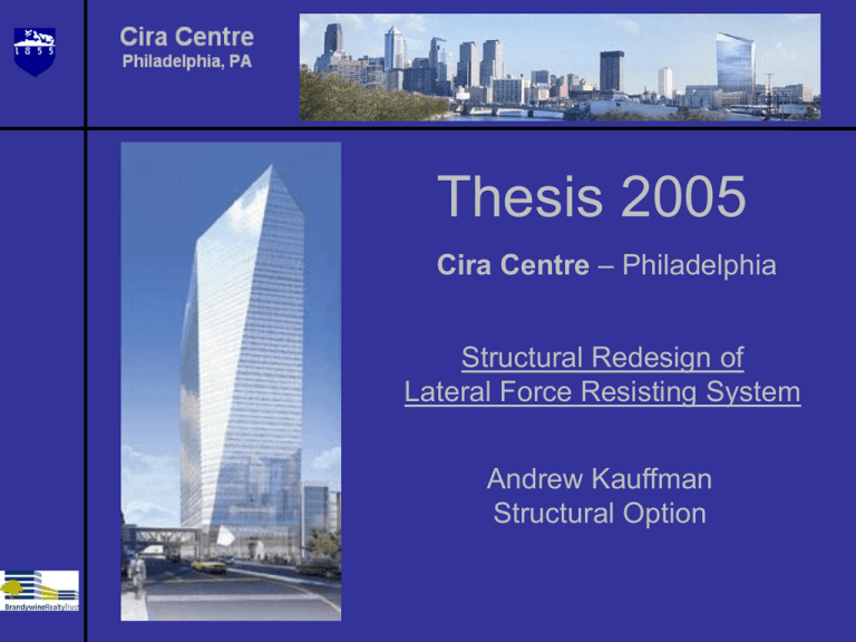
Thesis 2005 Cira Centre – Philadelphia Structural Redesign of Lateral Force Resisting System Andrew Kauffman Structural Option Presentation Outline Introduction Building Description Structural System Problem Statement Solution Overview Structural Redesign Mechanical Redesign Conclusion INTRODUCTION Introduction Adjacent to 30th Street Train Station - Philadelphia, PA 291,000 s.f., 28 story high rise office building Convention center, restaurants and retail space Tallest building in Philadelphia, outside Center City Scheduled for completion – October 2005 Total Projected Cost – $200 million BUILDING DESCRIPTION Building Description – Project Team Architects – Cesar Pelli and Assoc./Bower Lewis Thrower General Contractor – Turner Construction Co. Structural Engineer – Ingenium Inc. Civil Engineer – Pennoni Assoc. MEP Engineer – Jaros Baum and Bolles Lighting Design - Cline Bettridge Bernstein Acoustic Consultant - Cerami and Associates Curtain Wall Consultant - Israel Berger and Associates Building Description- Architectural Features 725,000 s.f. rentable space Open plan office levels: 727,725 s.f. (average) 9 ft. floor to ceiling heights Pedestrian bridge connecting to 30th Street train station Single point of entrance in main lobby, added security Highly reflective glass curtain wall Building Description – Building Systems Electrical – 13.2 KV primary voltage 480Y/277 volt, 3 phase, 4 wire Secondary system Mechanical – Fan powered, VAV system Includes 4 cooling towers located in top mezzanine Conveying – 14 high speed traction elevators Low-rise, mid-rise, high-rise Configuration STRUCTURAL SYSTEM Structural System – Overview Steel frame super-structure Composite floor system Drilled pier foundation Lateral System: Combination of braced and moment frames Structural System – Floor System Fully composite, 5 ¼ in. floor system, with LW concrete, metal decking, 50 ksi steel framing members W18x35 and W24x76 typical beams and girders, 30’x30’ bays, typ. 7'-11" 30' 30' 30' 30' 30' 30' 30' 7'-8" 12'-6" A 30' B N 30' C 30' D 12'-6" E F 1 2 3 4 5 6 7 8 9 10 Structural System – Vertical Framing Drilled concrete piers with up to 21.5’ penetration into bedrock Large built-up column sizes including W36x1202 wide flange members and 829 lb/ft. built-up box sections Forking Columns Leaning Columns Structural System – North/South Building Section 7'-11" 30' 30' 30' 30' 30' 30' 30' 7'-8" 12'-6" A 30' B N 30' C 30' D 12'-6" E F 1 2 3 4 5 6 7 8 9 10 North/South Section Structural System - East/West Section 7'-11" 30' 30' 30' 30' 30' 30' 30' 7'-8" 12'-6" A 30' B N 30' C 30' D 12'-6" E F 1 2 3 4 5 6 7 8 9 10 East-West Section MECH ROOM MACH ROOM MACH ROOM CONFERENCE Structural System – Lateral System East/West - Located in building core Combination of braced frames and moment connections A B LATERAL FRAMES ELEVATORS STAIR TOWERS N C LATERAL FRAME D E F 1 2 3 4 5 6 7 8 9 10 Structural System – Lateral System East – West Direction Along column lines C & D Located in structural core Exterior braced frames Interior moment frames Structural System – Lateral System North/South – Located in building core Combination of braced frames and moment connections A B LATERAL FRAMES ELEVATORS STAIR TOWERS N C LATERAL FRAME D E F 1 2 3 4 5 6 7 8 9 10 Structural System – Lateral System North - South Lateral System Along column lines 4 & 7 Located in Structural Core Exterior Moment Frames Interior Braced Frames Structural System – Lateral System North/South – Located along exterior frames Only moment frames A B LATERAL FRAMES ELEVATORS STAIR TOWERS N C LATERAL FRAME D E F 1 2 3 4 5 6 7 8 9 10 Structural System – Lateral System 28 27 26 25 24 23 22 21 20 19 18 17 16 15 14 13 12 11 10 9 8 7 6 5 4 3 2 North - South Lateral System Along column lines 1 & 10 All moment frames Varying stiffness PROBLEM STATEMENT Problem Statement – Overview Complicated Structure to Analyze • Varying Floor Geometry • Large built-up members Complicated Lateral System 1. Combination of braced and moment frames 2. Lateral frames with varying stiffness Problem Statement – Lateral Load Assumptions Lateral Loads used in actual design were developed using a wind tunnel analysis Wind Tunnel results yielded 65% of total shear and 75% of the overturning moment, compared to ASCE7-02, analytical method. Strength considerations did not control the original design of the building. Torsional acceleration at corner offices was the limiting factor that controlled the design SOLUTION OVERVIEW Solution Overview – Lateral System Redesign Develop wind and seismic loads based on ASCE7-02 Redesign Lateral System based on these loads. Compare cost of redesign to cost of original structure Solution Overview – Design Goals Gain a better understanding of lateral force resisting system design for steel buildings Investigate alternative lateral system configurations Meet the design criteria of IBC 2003. Limit interstory drift Limit overall building drift to L/400 criteria Achieve an economically feasible design Optimization of original design was not a goal Solution Overview - Procedure Develop wind loads using Analytical Procedure Model 2-D lateral frames using GT Struddle Determine relative stiffness based on virtual loads Distribute loads based on stiffness and torsion analysis Analyze frames for deflection and interstory drift Redesign lateral frames based on drift criteria - iterative Compare cost of redesign to original structural system Solution Overview – Mechanical Breadth Study Analyze feasibility of adding enthalpy wheels to the original mechanical system. Goal: Utilize the properties of building exhaust to save $$$ STRUCTURAL REDESIGN Structural Redesign – Stiffness Analysis Created model of each lateral frame in GT Struddle 100k virtual load at top of each frame to measure relative stiffness A B LATERAL FRAMES ELEVATORS STAIR TOWERS N C LATERAL FRAME D E F 1 2 3 4 5 6 7 8 9 10 Structural Redesign – East/West Lateral Frames Column Lines C & D Equal Stiffness Distribute half of total story load to each frame Equal distance from center of plan Torsion had minimal effect in this direction Structural Redesign – Load Distribution Structural Redesign - Results Total Deflection: 13.25” L/400 = 13.08” Acceptable based on occupancy comfort Structural Redesign – North/South Direction Modeled lateral frames along Column Lines 1,4,7,10 Applied Virtual Load at levels 28,20,10 A B LATERAL FRAMES ELEVATORS STAIR TOWERS N C LATERAL FRAME D E F 1 2 3 4 5 6 7 8 9 10 Structural Redesign – North/South Direction CL 1 CL 4/CL 7 CL 10 Structural Redesign – North/South Direction Relative stiffness varied with height. Applied uniform 10 kip load to verify stiffness Plotted results and fit equation Solved equation for stiffness in terms of height Relative Lateral Frame Stiffness 400 y = 23584x - 2049.3 350 Building Height (ft.) 300 CL4 250 CL10 CL1 200 Linear (CL1) y = 2088.6x - 122.41 Linear (CL10) 150 Linear (CL4) 100 y = -3839.6x + 1640.3 50 0 0 0.1 0.2 0.3 K - Relative Stiffness 0.4 0.5 Structural Redesign – North/South Direction Performed torsion analysis at each level based on center of rigidity Included 5% eccentricity per code, and determined loads on frames Level 20 A B N C Centre of Rigidty 21' 90 Kips D 1,900 Ft. Kips E F 1 2 3 4 5 6 390 PSF 7 7 8 10 Structural Redesign – North/South Direction Applied load to models in GT Struddle and analyzed results Structural Redesign – Results Each lateral frame deflected equal amounts. All frames deflected well over the L/400 limit. 19.99” 19.92” 17.16” Structural Redesign – Solution Alleviate interstory drift problems Limit overall building drift to 12” Started with exterior frames A B LATERAL FRAMES ELEVATORS STAIR TOWERS N C LATERAL FRAME D E F 1 2 3 4 5 6 7 8 9 10 Structural Redesign – North/South Direction Analyzed several bracing configurations using iterative procedure. Eliminated interstory drift problems, limited total drift to 12” Structural Redesign – North/South Direction Used same procedure for interior lateral frames along column lines 4 & 7 Could not limit drift to 12” A B LATERAL FRAMES ELEVATORS STAIR TOWERS N C LATERAL FRAME D E F 1 2 3 4 5 6 7 8 9 10 Structural Redesign – North/South Direction Increased stiffness of exterior lateral frames W14x145 bracing members Additional chevron braces to these frames Limited total drift to 9” Changed bracing of interior frames W14x159 bracing members Increased stiffness of girders to W33x221 Reapplied stiffness analysis and torsion calculations Calculated new story loads Results Structural Redesign – Cost Analysis Used R.S. Means to estimate total cost of original structure 20% total building cost = $ 40 million Performed take-off to calculate cost of lateral system redesign Compared additional cost to overall structural cost Cost Increase = 0.6% Structure Cost Cost Increase = 0.1% Structure Cost Mechanical Redesign Mechanical System Redesign System Description Fan powered VAV system Supply Air: 80% return, 20% outdoor air Exhaust: based on 150 cfm/toilet, 20 cfm/sink Typical Air Handler Size: 23,500 Procedure Use ASHRAE Bin data to analyze a full year cycle Based on 2 design condition: on peak – business hours, off peak – evenings and weekends Calculated total building load with/without use of enthalpy wheel Compared loads and calculate savings Mechanical System Redesign – Typical Floor Total Savings = Sensible Load savings + Latent Load savings Enthalpy wheels turned off when no energy is saved Additional energy can be saved by modulating wheel Mechanical System Redesign - Results Using Peco Energy Rates: Total Energy Savings: 671,236 kwh Total Cost Savings: $28,506/year CONCLUSION Conclusion Based on lateral load assumptions used for this analysis, the lateral frames in the North/South direction should be designed with increased stiffness based on occupancy comfort criteria. Redesign of lateral force resisting system is an economic solution compared to overall cost of structure Enthalpy wheels should be utilized by the mechanical system to increase overall efficiency and save $$$. Acknowledgments AE Faculty and Staff Dr. Memari and Dr. Geschwindner Dr. Hanangan and Prof. Parfitt Jeff Weinstein and Andy Bush, Brandywine Realty Trust Dr. Banavalker, Ingenium Inc. Peter Jennings, Jaros, Baum, and Bolles My Family and Friends My wife Nicole
