Intro to Post Frame Building Systems for Architects
advertisement

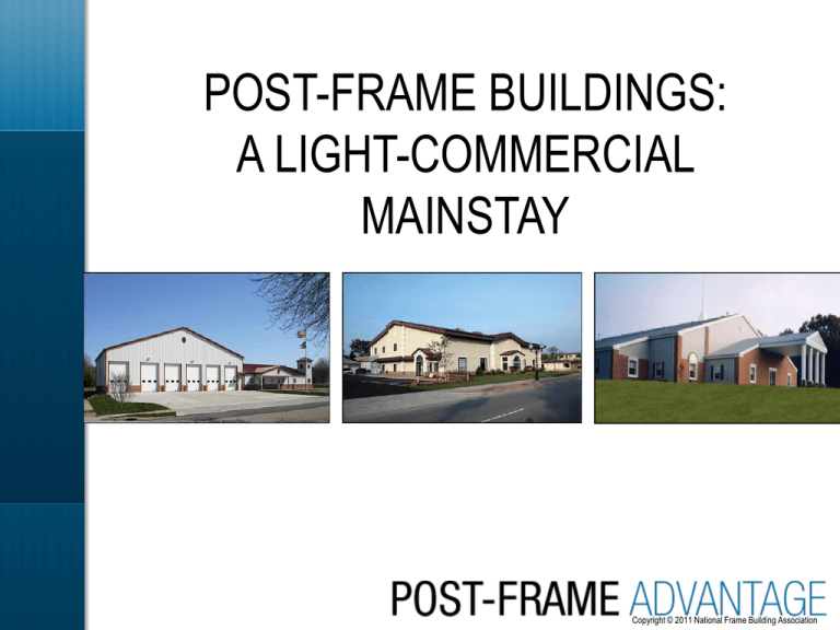
POST-FRAME BUILDINGS: A LIGHT-COMMERCIAL MAINSTAY Copyright © 2011 National Frame Building Association CONTINUING EDUCATION The National Frame Building Association is a Registered Provider with The American Institute of Architects Continuing Education Systems. This program is registered with the AIA/CES for continuing professional education. As such, it does not include content that may be deemed or construed to be an approval or endorsement by the AIA of any material of construction or any method or manner of handling, using, distributing, or dealing in any material or product. Questions related to specific materials, methods, and services will be addressed at the conclusion of this presentation. “With so many structural framing options, building functions, and architectural finishes, post-frame building systems are limited only by the architect’s imagination and creativity.” —Harvey Manbeck, PE PhD, professor emeritus at Penn State University and NFBA technical advisor Photo courtesy of Kistler Buildings Photo courtesy of Wick “Post-frame contributes very well to both the environment and the value for your dollar.” —Cheryl Ciecko, ALA AIA LEED AP CSI GGP, technical director, WoodWorks, a nonprofit initiative of the Wood Products Council Photo courtesy of Lester Building Systems, LLC Photo courtesy of Fingerlakes Construction Company LEARNING OBJECTIVES • Versatility and range of applications • Structural features that make these systems unique • Key performance characteristics • Resources for designing post-frame building systems Photo courtesy of Morton Buildings WHAT IS POST FRAME? Many architects and design professionals are unfamiliar with post frame. • It is not commonly included in traditional architectural school curricula. • They incorrectly equate post-frame construction with post-and-beam construction • They think post frame is only for agricultural buildings (i.e., barns, storage facilities, or horse facilities). POST FRAME IS EVERYWHERE Photo courtesy of Lester Building Systems, LLC CONVENIENCE STORES Photo courtesy of Lester Building Systems, LLC Photo courtesy of Wick Building Photo courtesy of Fbi Buildings RESTAURANTS Photo courtesy of Fbi Buildings COMMERCIAL OFFICE AND VETERINARY CLINICS Photo courtesy of Morton Buildings Photo courtesy of Morton Buildings RELIGIOUS SPACES Photo courtesy of Wick Buildings PRIVATE HOMES Photo courtesy of Morton Buildings PUBLIC BUILDINGS Photo courtesy of Lester Building Systems, LLC and SL Construction Photo courtesy of Morton Buildings COMMUNITY BUILDINGS Photo courtesy of Kistler Buildings Photo courtesy of Little Construction Co., Inc. RECEPTION HALLS Photo courtesy of Lester Building Systems, LLC and Eastern Iowa Building, Inc. Photo courtesy of Lester Building Systems, LLC and Eastern Iowa Building, Inc. RETAIL STORES Photo courtesy of Lester Building Systems, LLC POST-AND-BEAM CONSTRUCTION Pinned Connection Girder (Beam) Post Concrete Pier Continuous Footer or Pier Foundation Floor POST-AND-BEAM CONSTRUCTION Post Girder (Beam) Purlin THIS IS POST FRAME Truss-to-Post Connection Primary frames Wood Column Clear span truss Embedded Post Foundation Figure 1. Post-frame building with trusses supported by embedded posts Roof Purlin THIS IS POST FRAME Wall Girt Figure 2. Post-frame building mounted on a concrete stem wall PRIMARY FEATURES OF POST FRAME Sheathing Purlins Truss Wood columns Wall girts PRIMARY FEATURES OF POST FRAME THIS IS POST FRAME—PLAN VIEW Purlin Post Girder (Header) Clear Span Truss KEY FEATURES OF POST FRAME Truss X-section Girts Purlins Sidewall Post Post Height Eave Height Splashboard Clear Span Post Foundation Post Footing KEY FEATURES OF POST FRAME • • • • • wood sidewall columns wide bay spacing—8 ft and greater large clear spans—over 100 ft embedded wood columns or concrete piers attached wall and roof sheathing or cladding form structural shearwall/structural diaphragm system for resisting lateral loads WOOD SIDEWALL COLUMNS • Solid-sawn, glued-laminated, or mechanically (nail) laminated wood • Nominal 6x6, 6x8, 8x8, or 8x10 cross section • Typically spaced 4, 6, 8, 12, or 16 ft on center along sidewall • Any portion of the wood post embedded directly into the ground and 6–12 in. above grade is pressure preservative treated to AWPArecommended levels for ground contact WOOD SIDEWALL COLUMN Spliced glued-laminated column • 3- or 4-ply, fabricated with 2x lumber • lower portion is preservative treated • upper portion is untreated WOOD SIDEWALL COLUMNS Nail-laminated posts with treated bottom spliced to untreated top Preservativetreated splash board WOOD SIDEWALL COLUMNS Untreated Post Concrete Pier PRESSURE PRESERVATIVE TREATMENTS • Posts embedded in the ground, specify: • use category UC4B or better per AWPAU1-09 • e.g., CCA@0.60 pcf POST FOUNDATION OPTIONS: EMBEDDED TREATED COLUMNS Treated PRECAST OR CAST-IN-PLACE REINFORCED CONCRETE PIER • Pre-cast reinforced concrete pier with post attached above grade • Entire assembly preengineered • Assembly usually fabricated in factory and shipped to site as a single unit PRE-CAST REINFORCED CONCRETE PIER Reinforcement Cleat Cast-in-Place Concrete Foundation Wall CAST-IN-PLACE CONCRETE FOUNDATION WALL Untreated Post Connection Hardware THICKENED CONCRETE SLAB THICKENED CONCRETE SLAB PROTECTIVE POST COVERS • Blow-molded plastic or HDPE plastic protective barriers • Provide moisture and insect protection • “Enhance protection of copperbased chemical treated wood posts or laminated columns” ROOF FRAMING • Pre-engineered metal plate connected 2x lumber trusses typically spaced 4–8 ft on center • Heavier timber trusses for larger post and truss spacings and aesthetic requirements • Solid-sawn wood rafters spaced 2–4 ft on center for shorter clear spans • Glulam rafters for larger rafter spacings or clear spans ROOF FRAMING Trusses Sidewall Post (connected to trusses) POST TO ROOF FRAMING CONNECTIONS • Posts are connected directly to the roof framing if post and roof framing spacing are the same • Posts and roof framing are often connected to header beams if post and roof framing spacing are not the same POST TO ROOF FRAMING CONNECTION Block Height Block Connection is usually a pinned connection (not a moment-resisting connection). POST TO ROOF FRAMING CONNECTION POST TO ROOF FRAMING CONNECTION SOLID SAWN POSTS Typical post to truss connection details for a solid sawn post application Connection with truss fastened to slide of post and with bear block 1½” Connection with truss bearing on notch in post POST TO ROOF FRAMING CONNECTION • Schematic of typical connection details • Truss to header (girder) • Header (girder) to roof POST TO ROOF FRAMING CONNECTION Metal Plate Connector Header (Girder) Blocking ROOF PURLIN PLACEMENT Purlins oriented flat or “on edge,” depending on truss and purlin spacing Purlins placed either on top or inset between truss top chords or inset between roof rafters ROOF FRAMING AND PURLINS Purlin 2 ft o.c. 8 ft o.c. Connection to Post Connection Truss WALL GIRTS • Typically 2x4 to 2x8 solid sawn lumber, spaced 24–32 in. apart • Oriented “flat” on outside face of wall post for smaller post and girt spacings and loads • “On edge” between adjacent posts for larger loads or post or girt spacings WALL GIRTS AND SHEATHING Wall Girt Sheating WALL GIRTS AND SHEATHING SECONDARY FRAMING AND BRACING • • • • • Corner bracing in upper chords of trusses Diagonal bracing for lower chords of trusses Lower chord stiffeners for trusses Cross bracing of selected compression webs Continuous longitudinal bracing of long compression webs and chords of trusses TRUSS BRACING • Guide to Good Practices for Handling, Installing, Restraining & Bracing of Metal-Plate Connected Wood Trusses (WTCA and TPI) • B1 and B3 summary sheets: handling and bracing trusses • B10 summary sheet: Post-frame truss installation and bracing UNIQUE FEATURES OF PF The most economical combination has • laminated wood sidewall and endwall columns • embedded post or embedded concrete pier foundations • metal-plate connected 2x wood roof trusses and • 26- to 29-gauge ribbed steel roof and wall sheathing PF TECHNICAL RESOURCES • ANSI/ASAE (ASABE) EP 484 for diaphragm design of metal-clad, post-frame rectangular buildings • ANSI/ASAE (ASABE) EP 486 for shallow post foundation design • ANSI/ASAE (ASABE) EP 559 for design requirements and bending properties for mechanically laminated columns PF BUILDING DESIGN MANUAL • Structural design procedures for PF building systems – PF designer’s primary reference – www.NFBA.org BENEFITS OF POST FRAME • • • • • • Cost-effective Energy efficient Code compliance Sustainability and greenness Design flexibility Durability and strength MORE ABOUT POST FRAME • National Frame Building Association (NFBA) • www.PostFrameAdvantage.com • www.NFBA.org • NFBA 4700 W Lake Ave Glenview, IL 60025 QUESTIONS AND COMMENTS? • National Frame Building Association (NFBA) • www.NFBA.org • www.PostFrameAdvantage.com • NFBA 4700 W Lake Ave Glenview, IL 60025 PREPARED BY HARVEY B. MANBECK, P.E., PHD PROFESSOR EMERITUS PENN STATE UNIVERSITY COPYRIGHT @ 2011 BY THE NATIONAL FRAME BUILDING ASSOCIATION


