Stefan-Boltzmann’s law of radiation with Cobra3
TEP
Related topics
Black body radiation, thermoelectric e.m.f. (electro motive force), temperature dependence of resistances.
Principle and task
The energy emitted by a black body per unit area and unit time is proportional to the fourth power of the
body's absolute temperature (Stefan-Boltzmann law). This is also valid for a grey body. A grey body has
a surface with a wavelength-independent absorption coefficient of less than one. In this experiment the
filament of an incandescent lamp is taken as a model for a grey body and its emission is investigated as
a function of its temperature.
Equipment
1 Cobra3 Basic Unit, USB
1 Power supply, 12 V1 Cobra3 Universal Writer Software
1 Thermopile, molltype
1 Shielding tube, for thermopile
1 Power supply var.15VAC/12VDC/5A
1 Lamp holder E 14, on stem
3 Filament lamp 6 V/5 A, E14
1 Connection box
1 Resistor in plug-in box 100 Ohm
1 Digital multimeter
2 Connecting cord, 500 mm, blue
3 Connecting cord, 500 mm, red
2 Barrel base PHYWE
1 Meter scale, l = 1000 mm
PC, Windows® 95 or higher
12150-50
12151-99
14504-61
08479-00
08479-01
13530-93
06175-00
06158-00
06030-23
06057-10
07129-00
07361-04
07361-01
02006-55
03001-00
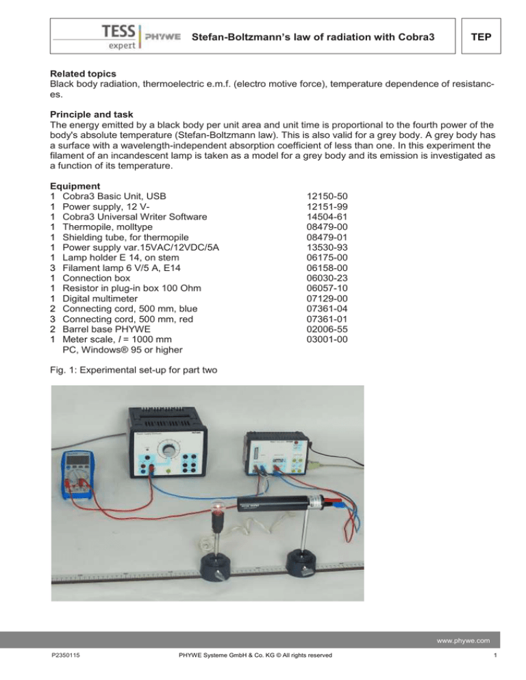
Fig. 1: Experimental set-up for part two
www.phywe.com
P2350115
PHYWE Systeme GmbH & Co. KG © All rights reserved
1
TEP
Stefan-Boltzmann’s law of radiation with Cobra3
Tasks
1. Measure the resistance of the filament of the incandescent lamp at room temperature and calculate
the filament's resistance 𝑅0 at 0°C.
2. Measure the energy flux density of the incandescent lamp at different values of lamp current. Determine the corresponding filament temperature by the resistance calculated from the measured values
of lamp current and lamp voltage assuming a second-order temperature dependence of the filament
resistance.
Set-up and Procedure
1. Connect the Cobra3 Basic Unit to the computer USB port and start the program "measure". Select
"Gauge" > "Universal Writer". Select the "Fast measurement" chart and set the parameters according
to Fig. 2.
Fig. 2: Universal Writer settings
First measure the lamp filament's resistance at room temperature using the circuit shown in Fig.3. For
the set-up of the circuit use the connection box and the 100 Ohm resistor.
The voltage 𝑈 on the lamp is to be measured with the "Analog In 1 / S1" and the current I through the
lamp with the digital multimeter. Use the power supply as AC source. The 100 Ohm resistor is needed to
reduce the current and thus to allow its fine adjustment. Be sure you use the "AC" setting of the digital
multimeter. Adjust the current to 100 mA AC and start the measurement with the "Continue" button.
After ending the measurement use the "Survey" function to evaluate the peak-to-peak voltage. The function "Analysis" > "Smooth" may help with the evaluation to improve the visibility of the peaks.
2
PHYWE Systeme GmbH & Co. KG © All rights reserved
P2350115
Stefan-Boltzmann’s law of radiation with Cobra3
TEP
Fig. 3: Circuit for measuring the resistance of the lamp at room temperature.
Divide the peak-to-peak voltage by two and by the square root of two to determine the effective voltage
on the lamp.
Do the same for a lamp current of 50 mA AC. These currents should be low enough not to considerably
heat the filament. Calculate the resistance R(tR) at room temperature tR (in °C) (by Ohm's law R = U/I)
and from this value the resistance at 0°C 𝑅0 by
𝑅0 = 𝑅(𝑡𝑅 ) / (1 + 𝛼 𝑡𝑅 + 𝛽 𝑡𝑅2 )
with
𝛼 = 4.82 · 10−3 K-1 and
𝛽 = 6.67 · 10−7 K-2.
𝛼 and 𝛽 are material constants of tungsten.
2. Remove the protective window of the thermopile, since this has only a low permeability for IRradiation. Set up the equipment according to Fig. 1 and align the thermopile in a way that it receives
the lamp's radiation with the distance between lamp and thermopile less than 20 cm. The helix of the
filament should be at right angle to the thermopile. Take care that the thermopile is connected to the
positive and negative terminal of the input “Analog In 2/S2” rather than positive terminal and ground to
avoid the unwanted oscillation of the thermal voltage at the mains frequency.
The digital multimeter is to measure the current through the lamp and "Analog In 1 / S1" is to measure
the voltage on the lamp. Make sure that the thermopile could adapt to the ambient temperature in order to avoid a zero drift of the measured values.
Set the AC current so that the digital multimeter shows 1 A. Wait a minute until the thermopile has
tempered and start a measurement with the "Continue" button.
www.phywe.com
P2350115
PHYWE Systeme GmbH & Co. KG © All rights reserved
3
Stefan-Boltzmann’s law of radiation with Cobra3
TEP
Increase the current through the lamp in steps of 0.5 A taking a measurement for each current
strength up to 5.5 A. U2 is proportional to the energy flux from the lamp if there are no other sources
detected by the thermopile as disturbing background.
Wait always at least one minute for tempering of the thermopile.
For evaluation use the function "Survey" to measure the amplitude of "Analog In 1" voltage U1 in the
just recorded measurement (see Fig. 4). Take down the effective value, which is the amplitude (half
the peak-to-peak value) divided by the square root of two. Use the "Show average value" function to
evaluate the "Analog In 2" voltage U2. Note down both results in the "measure" program using
"Measurement" > "Enter data manually…" with the current I as x-data set and two channels (for U1
and U2) – measure the new values and continue with the next current step.
Theory and evaluation
If the energy flux density 𝐿 of a black body, e.g. energy emitted per unit area and unit time at temperature 𝑇 and wavelength 𝜆 within the interval 𝑑𝜆, is designated by 𝑑𝐿(𝑇, 𝜆)/𝑑𝜆,
Planck’s formula states:
𝑑𝐿 (𝜆,𝑇)
𝑑𝜆
=
with:
2𝑐 2 ℎ𝜆−5
𝑒
(1)
ℎ𝑐 −1
𝜆𝑘𝑡
𝑐 = velocity of light
(3.00 · 108 [m/s])
ℎ = Planck’s constant
(6.62 · 10−34 [J · s])
𝑘 = Boltzmann’s constant
(1.381 · 10−23 [J · K −1])
Integration of equation (1) over the total wavelength-range from 𝜆 = 0 to 𝜆 = ∞ gives the flux density L(T)
(Stefan-Boltzmann’s law).
𝐿(𝑇) =
2𝜋5
15
∙
𝐾4
𝑐 2ℎ3
∙ 𝑇4
(2)
respectively 𝐿(𝑇) = 𝜎 · 𝑇 4
with 𝜎 = 5.67 · 10–8 [W · m–2 · K–4]
4
PHYWE Systeme GmbH & Co. KG © All rights reserved
P2350115
Stefan-Boltzmann’s law of radiation with Cobra3
TEP
Fig. 4: Example for the use of the "Survey function" for evaluation – the amplitude is half the peak-topeak value
The proportionality 𝐿 ~ 𝑇 4 is also valid for a so-called “grey” body whose surface shows a wavelengthindependent absorption-coefficient of less than one.
To prove the validity of Stefan-Boltzmann’s law, we measure the radiation emitted by the filament of an
incandescent lamp which represents a “grey” body fairly well. For a fixed distance between filament and
thermopile, the energy flux ϕ which hits the thermopile is proportional to 𝐿(𝑇).
ϕ ~ 𝐿(𝑇)
Because of the proportionality between ϕ and the thermoelectric e.m.f., 𝑈therm of the thermopile, we can
also write:
𝑈therm ~ 𝑇 4
if the thermopile is at a temperature of zero degrees Kelvin. Since the thermopile is at room temperature
TR it also radiates due to the T4 law so that we have to write:
𝑈therm ~ (𝑇 4 − 𝑇𝑅4 )
Under the present circumstances, we can neglect 𝑇𝑅4 against 𝑇 4 so that we should get a straight line with
slope “4” when representing the function 𝑇therm = 𝑓(𝑇) double logarithmically.
lg 𝑈therm = 4 lg 𝑇 + const.
(3)
You may have measured negative thermo voltages for small lamp currents, due to insufficient time to
adapt the temperature of the thermopile or interference.
Since the logarithm is defined only for numbers greater than zero, you have to raise all thermoelectric
voltages measured evenly.
The absolute temperature 𝑇 = 𝑡 + 273 of the filament is calculated from the measured resistances 𝑅(𝑡)
of the tungsten filament (𝑡 = temperature in centigrade). For the tungsten filament resistance, we have
the following temperature dependence:
www.phywe.com
P2350115
PHYWE Systeme GmbH & Co. KG © All rights reserved
5
Stefan-Boltzmann’s law of radiation with Cobra3
TEP
𝑅(𝑡) = 𝑅0 (1 + 𝛼𝑡 + 𝛽𝑡 2 )
(4)
with 𝑅0 = resistance at 0°C
𝛼 = 4.82 · 10−3 𝐾 −1
𝛽 = 6.76 · 10−7 𝐾 −2
Fig. 5
The resistance 𝑅0 at 0°C can be found by using the relation:
𝑅0 =
𝑅(𝑡𝑅 )
2
1+ 𝛼 ∙ 𝑡𝑅 + 𝛽 ∙ 𝑡𝑅
(5)
Solving 𝑅(𝑡) with respect to t and using the relation 𝑇 = 𝑡 + 273 gives:
𝑇 = 273 +
1
2𝛽
𝑅(𝑡)
[√𝛼 2 + 4𝛽 ( 𝑅 − 1) − 𝛼]
0
(6)
(6)
𝑅(𝑡𝑅 ) and 𝑅(𝑡) are found by applying Ohm’s law, e. g. by voltage and current measurements across the
filament.
For evaluation of the data add the calculated resistance 𝑅(𝑡) as a new channel to the manually created
measurement by "Analysis" > "Channel modification…" dividing the "Analog In 1 / S1" values, i.e. the
voltage on the lamp 𝑈1 , by the current 𝐼 values. Add the temperature 𝑇, which was calculated
from the resistance values, to that measurement in the same manner: Equation (6) has to be written in a
form suitable for the channel modification with the actual symbol for 𝑅 and the numerical value for 𝑅0 inserted (which was measured in 1.) like
𝑓 ∶= 273 + 7496,25 ∗ ((0,2323 + 0,02704 ∗ (𝑅/𝑅0 – 1))^0,5 – 0,482).
See Fig. 5 and Fig. 6 (in this case is 𝑅0 = 0.16 Ohm).
6
PHYWE Systeme GmbH & Co. KG © All rights reserved
P2350115
Stefan-Boltzmann’s law of radiation with Cobra3
TEP
Now use "Measurement" > "Channel manager…" and set the temperature data to the x-axis so as to
create a plot of the thermopile voltage vs. temperature 𝑇. A result may look like Fig. 7.
Fig. 6
The following table shows the corresponding measurement values, the resistance 𝑅0 was calculated as
0.16 Ohm, and the slope of the regression line is with 3.97 close to the theoretical value of four for the
exponent of Stefan-Boltzmann's law.
www.phywe.com
P2350115
PHYWE Systeme GmbH & Co. KG © All rights reserved
7
TEP
Stefan-Boltzmann’s law of radiation with Cobra3
Fig. 7: Example of measurement results
8
PHYWE Systeme GmbH & Co. KG © All rights reserved
P2350115

