t ≥ 0
advertisement
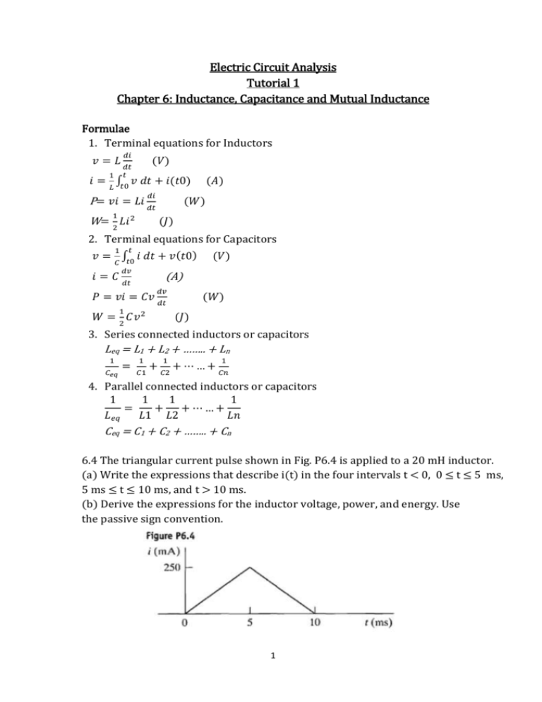
Electric Circuit Analysis Tutorial 1 Chapter 6: Inductance, Capacitance and Mutual Inductance Formulae 1. Terminal equations for Inductors 𝑣=𝐿 𝑖= 𝑑𝑖 𝑑𝑡 1 𝑡 ∫ 𝑣 𝐿 𝑡0 (𝑉) 𝑑𝑡 + 𝑖(𝑡0) 𝑑𝑖 P= 𝑣𝑖 = 𝐿𝑖 𝑑𝑡 (𝐴) (𝑊) 1 W= 2 𝐿𝑖 2 (𝐽) 2. Terminal equations for Capacitors 𝑡 1 𝑣 = ∫𝑡0 𝑖 𝑑𝑡 + 𝑣 (𝑡0) 𝐶 𝑖=𝐶 𝑑𝑣 (𝑉) (A) 𝑑𝑡 𝑃 = 𝑣𝑖 = 𝐶𝑣 𝑑𝑣 (𝑊) 𝑑𝑡 1 𝑊 = 𝐶𝑣 2 (𝐽) 2 3. Series connected inductors or capacitors Leq = L1 + L2 + …….. + Ln 1 𝐶𝑒𝑞 = 1 𝐶1 + 1 𝐶2 + ⋯…+ 1 𝐶𝑛 4. Parallel connected inductors or capacitors 1 1 1 1 = + + ⋯…+ 𝐿𝑒𝑞 𝐿1 𝐿2 𝐿𝑛 Ceq = C1 + C2 + …….. + Cn 6.4 The triangular current pulse shown in Fig. P6.4 is applied to a 20 mH inductor. (a) Write the expressions that describe i(t) in the four intervals t < 0, 0 ≤ t ≤ 5 ms, 5 ms ≤ t ≤ 10 ms, and t > 10 ms. (b) Derive the expressions for the inductor voltage, power, and energy. Use the passive sign convention. 1 Solution: (a) i = 0 , t < 0 To find i, from 0 ≤ t ≤ 5 ms we have to use the equation of line (0 , 0) (5 , 250) 𝑦 − 𝑦1 = i−0 = 𝑦1−𝑦2 𝑥1−𝑥2 0−250𝑚𝑠 0−5𝑚𝑠 (𝑥 − 𝑥1) (𝑡 − 0) i = 50 t A For 5 ms ≤ t ≤ 10 ms , (5 , 250) (10 , 0) i−250𝑚𝑠 = 250𝑚𝑠−0 5𝑚𝑠−10𝑚𝑠 (𝑡 − 5𝑚𝑠) i – 250m = - 50 (t – 5m) i = - 50t + 250m + 250m i = - 50t + 0.5 A i = 0 , t > 10 ms (b) t < 0, 𝑣 = 𝐿 𝑑𝑖 𝑑𝑡 = 20 × 10−3 0 ≤ t ≤ 5 ms, 𝑣 = 20 × 10−3 5 ms ≤ t ≤ 10 ms, 𝑣 = 𝑑𝑡 (0) = 0 𝑉 (50𝑡) = 20 × 10−3 × 50 = 1 𝑉 𝑑𝑡 𝑑 20 × 10−3 (−50𝑡 𝑑𝑡 −3 𝑑 t > 10 ms, 𝑣 = 20 × 10 P = vi t < 0, 0 ≤ t ≤ 5 ms, 5 ms ≤ t ≤ 10 ms, t > 10 ms, 𝑑 𝑑 𝑑𝑡 + 0.5) = 20 × 10−3 × −50 = −1 𝑉 (0) = 0 𝑉 P = 0*0 = 0 W P = 1V*50 t = 50 t W P = - 1V*(-50 t + 0.5) = (50 t – 0.5) W P = 0*0 = 0 W 𝑡 W = ∫𝑡0 𝑃𝑑𝑡 + 𝑊(0) t < 0, 0 ≤ t ≤ 5 ms, 5 ms ≤ t ≤ 10 ms, t > 10 ms, 𝑡 W = ∫−∞ 0𝑑𝑡 = 0 J 𝑡 W = ∫0 50𝑡 𝑑𝑡 + 0 = 50 W= 𝑡 ∫5𝑚𝑠(50𝑡 𝑡2 2 𝑡 ∫0 = 25 𝑡 2 𝐽 − 0.5) 𝑑𝑡 + 𝑊(5𝑚𝑠) 𝑡 W = ∫10𝑚𝑠 0𝑑𝑡 = 0 J 2 6.6 The current in a 20 mH inductor is known to be i = 40 mA, t ≤ 0; −10,000t −40,000t i =A1 e + A2 e , t≥0 The voltage across the inductor (passive sign convention) is 28 V at t = 0. a) Find the expression for the voltage across the inductor for t > 0. b) Find the time, greater than zero, when the power at the terminals of the inductor is zero. Solution: t = 0 , i (0) = A1 * 1 + A2 * 1 = A1 + A2 i (0) = 40 mA = 0.04 A1 + A2 = 0.04 A1 = 0.04 – A2 𝑑𝑖 𝑑𝑡 v=𝐿 ……………. ( 1 ) = A1 e−10,000t (−10,000) + A2 e−40,000t (−40,000) 𝑑𝑖 𝑑𝑡 = 20*10-3(-10,000A1 e−10,000t − 40,000 A2 e−40,000t ) v = − 200 A1 e−10,000t − 800 A2 e−40,000t v (0) = - 200 A1 – 800 A2 v (0) = 28 V - 200 A1 – 800 A2 = 28 Substitute A1 = 0.04 – A2 - 200 (0.04 – A2) – 800 A2 = 28 - 600 A2 = 28 + 8 A2 = - 36/600 = - 0.06 A1 = 0.04 – (- 0.06) = 0.1 i = 0.1 e−10,000t − 0.06e−40,000t v = - 200*0.1 e−10,000t − 800 ∗ (−0.06e−40,000t ) v = −20e−10,000t + 48e−40,000t , t≥0 (b) For P = 0 either i = 0 or v= 0 i=0 0.1 e−10,000t − 0.06e−40,000t = 0 0.1 e−10,000t = 0.06e−40,000t e−10,000t+40,000t = 0.06 0.1 3 e30,000t = 0.6 30,000t = ln (0.6) t = - 17.03 µs which is not possible. v=0 −20e−10,000t + 48e−40,000t = 0 e−10,000t+40,000t = 48 20 e30,000t = 2.4 30,000t = ln (2.4) t = 29.18 µs The power is zero at t = 29.18 µs. 6.13 Initially there was no energy stored in the 5 H inductor in the circuit in figure. P6.13 when it was placed across the terminals of the voltmeter. At t = 0 the inductor was switched instantaneously to position b where it remained for 1.6 s before returning instantaneously to position a. The d’Arsonval voltmeter has a full-scale reading of 20 V and a sensitivity of 1000 Ώ/V. What will the reading of the voltmeter be at the instant the switch returns to position a if the inertia of the d’Arsonval movement is negligible? Solution: For 0 ≤ t ≤ 1.6 s; 1 𝑡 iL = 𝐿 ∫0 𝑣𝐿 𝑑𝑡 + 𝑖 (0) = 𝑡 ∫ 3 5 0 1 × 10⁻³ 𝑑𝑡 + 0 = 0.6 × 10⁻³ 𝑡 iL (1.6 s)= 0.6 × 10⁻³ (1.6) = 0.96 mA Rm = Resistance of the voltmeter = 𝑉𝐹𝑠 × 𝑆𝑒𝑛𝑠𝑖𝑡𝑖𝑣𝑖𝑡𝑦 = 20𝑉 × 1000Ώ/𝑉 = 20 𝑘Ώ 𝑣𝑚 (1.6𝑠) = 𝑖𝐿 × 𝑅𝑚 = 0.96 × 10−3 × 20 × 103 = 19.2 𝑉 AP 6.2 The voltage at the terminal of the 0.6 µF capacitor shown in the figure is 0 for t < 0 and 40 𝑒 −15,000𝑡 𝑠𝑖𝑛30,000𝑡 𝑉 𝑓𝑜𝑟 𝑡 ≥ 0. 𝐹𝑖𝑛𝑑 (a) i(0) ; (b) the power delivered to the capacitor at t = 𝜋/80 ms; and (c) the energy stored in the capacitor at t = 𝜋/80 ms 4 Solution: (a) i = 𝐶 𝑑𝑣 = 0.6 × 10⁻⁶ 𝑑𝑡 −6 ( −15,000𝑡 𝑑 𝑑𝑡 (40 𝑒 −15,000𝑡 𝑠𝑖𝑛30,000𝑡 ) 𝑒 𝑐𝑜𝑠30,000𝑡 (30,000) + 𝑒 −15,000𝑡 (−15,000)𝑠𝑖𝑛30,000𝑡 ) = 𝑒 −15,000𝑡 (0.72 𝑐𝑜𝑠30,000𝑡 − 0.36 𝑠𝑖𝑛30,000𝑡 𝐴 i(0) = 0.72 = 24 × 10 𝜋 −3 (b) i(π/80 ms) = 𝑒 −15,000×80×10 (0.72 cos(30,000 × 𝜋 80 × 10−3 𝑡) 𝜋 80 × 10−3 ) − 0.36 sin(30,000 × = - 31.66× 10⁻³ 𝐴 𝜋 −3 v (π/80 ms) = 40 𝑒 −15,000×80×10 sin(30,000 × 𝜋 80 × 10−3 ) = 20.505 V p = vi = - 31.66× 10−3 ×20.505 = - 649.23 mW 1 1 2 2 (c) w = 𝐶𝑣 2 = 0.6 × 10⁻⁶ (20.505)2 = 126.13 𝜇𝐽 6.21 Assume that the initial energy stored in the inductor of figure. P6.21 is zero. Find the equivalent inductance with respect to the terminals a,b. Solutions: 5 ǁ (12 + 8) = 5 ǁ 20 = 5×20 5+20 =4 𝐻 4 H ǁ 4 H = 4/2 H = 2 H 15 ǁ (8 + 2) = 15 ǁ 10 = 3ǁ6= 3×6 3+6 15×10 15+10 =2H Leq = 2 + 6 = 8 H 5 =6 𝐻 6.23 The three inductors in the circuit in figure. P6.23 are connected across the terminals of a black box at t=0. The result voltage for t > 0 is known to be va = 2000𝑒 −100𝑡 𝑉. If i1 (0) = - 6 A and i2 (0) = 1 A, find a) io(0) b) io(t), t ≥ 0 c) i1(t), t ≥ 0 d) i2(t), t ≥ 0 e) the initial energy stored in the three inductors f) the total energy delivered to the black box, and g) the energy trapped in the ideal conductors. Solution: (a) io(0) = - i1(0) – i2(0) = - (-6) – 1 = 5 A (b) 1 H ǁ 4 H = 1×4 1+4 = 0.8 𝐻 0.8 H + 3.2 H = 4 H. the equivalent circuit will be 𝑡 1 𝑖𝑜 (𝑡) = − ∫ 𝑣 𝑑𝑡 + 𝑖𝑜 (0) 𝐿 0 𝑖𝑜 (𝑡) = − 1 𝑡 ∫ 2000𝑒 −100𝑡 𝑑𝑡 + 5 4𝐻 0 (c) To find i1 (t), draw he circuit for t > 0 𝑣𝑎 = 𝐿 𝑑𝑖𝑜 𝑑𝑡 = 3.2 𝐻 𝑑 𝑑𝑡 (5 𝑒 −100𝑡 ) = 16 𝑒 −100𝑡 (−100) = −1600 𝑒 −100𝑡 𝑉 From KVL, - vc + vb + va = 0 6 vc = va + vb = −1600 𝑒 −100𝑡 + 2000𝑒−100𝑡 = 400 𝑒−100𝑡 𝑖1 (𝑡) = 𝑡 1 ∫ 400𝑒 −100𝑡 𝑑𝑡 − 6 = 400 1𝐻 0 𝑒 −100𝑡 - 6 −100 = - 4 (𝑒 −100𝑡 − 1) – 6 = - 4 𝑒 −100𝑡 − 2 𝐴 , (d) 𝑖2 (𝑡) = 𝑡 1 ∫ 400𝑒 −100𝑡 𝑑𝑡 + 1 = 100 4𝐻 0 𝑒 −100𝑡 +1 −100 = - 1 (𝑒 −100𝑡 − 1) + 1 = − 𝑒 −100𝑡 + 2 𝐴, 1 1 = 1(6)2 + 2 1 1 2 2 t ≥ 0 1 𝐿 𝑖 2 + 𝐿𝑜 𝑖𝑜 2 2 2 2 2 1 1 4(1)2 + 3.2 (5)2 2 2 (e) Initial energy stored W(0) = 𝐿1 𝑖1 2 + 2 t≥0 1 = 60 𝐽 (f) Wdel = 𝐿𝑒𝑞 𝑖𝑜 2 = 4(5)2 = 50 𝐽 (g) ) Wtrapped = W(0) − 𝑊𝑑𝑒𝑙 = 60 − 50 = 10 𝐽 1 1 2 2 Or Wtrapped = 𝐿1 𝑖1𝑑𝑐 2 + 𝐿2 𝑖2𝑑𝑐 2 = 1 2 1(2)2 + 1 2 4(2)2 = 10 𝐽 (𝑐ℎ𝑒𝑐𝑘) 6.31 the two series-connected capacitors in figure. P6.31 are connected to the terminals of a black box a t= 0. The resulting current i(t) for t > 0 is known to be 800 𝑒 −25𝑡 𝜇𝐴. (a) Replace the original capacitors with an equivalent capacitor and find vo(t), for t ≥ 0. (b) Find v1(t), for t ≥ 0. (c) v2(t), for t ≥ 0. (d) How much energy is delivered to the black box in the time interval 0 ≤ t < ∞ (e) How much energy was initially stored in the series capacitors. (f) How much energy is trapped in the ideal capacitors? (g) Show that the solutions for v1 and v2 agree with the answers obtained in (f). Solution: 8 𝜇𝐹 is in series with 2 𝜇𝐹 𝐶𝑒𝑞 = Veq = + 25 V – 5 V = 20 V 7 𝐶1×𝐶2 𝐶1+𝐶2 = 8 𝜇𝐹×2 𝜇𝐹 8 𝜇𝐹+2 𝜇𝐹 = 1.6 𝜇𝐹 𝑡 1 𝑣𝑜 (𝑡) = ∫ 𝑖 𝑑𝑡 + 𝑣𝑜 (0) 𝐶 0 𝑡 1 ∫ 800 𝑒 −25𝑡 × 10−6 𝑑𝑡 + 20 𝑣𝑜 (𝑡) = −6 1.6 × 10 0 𝑒 −25𝑡 = 500 × − 20 −25 = - 20 (𝑒 −25𝑡 − 1) – 20 = − 20 𝑒 −25𝑡 𝑉, 1 (b) 𝑣1 (𝑡) = 𝑡 ∫ 800 𝑒 −25𝑡 × 10−6 𝑑𝑡 + 5 2×10⁻⁶ 0 𝑒 −25𝑡 = 400 × 𝑡≥0 +5 −25 = - 16 (𝑒 −25𝑡 − 1) + 5 = − 16𝑒 −25𝑡 + 21 𝑉, (c) 𝑣2 (𝑡) = 𝑡 1 ∫ 800 8×10⁻⁶ 0 𝑒 −25𝑡 = 100 × 𝑡≥0 𝑒 −25𝑡 × 10−6 𝑑𝑡 − 25 − 25 −25 = −4(𝑒 −25𝑡 − 1) − 25 = −4 𝑒 −25𝑡 − 21 𝑉, 𝑡≥0 (d) 𝑝 = −𝑣𝑖 = −(− 20 𝑒 −25𝑡 )(800 𝑒 −25𝑡 × 10−6 ) = 16 × 10−3 𝑒 −50𝑡 𝑊 ∞ ∞ 𝑤 = ∫0 𝑝 𝑑𝑡 = ∫0 16 × 10−3 𝑒 −50𝑡 𝑑𝑡 = 16 × 10−3 = −0.32 × 10 −3 𝑒 −50𝑡 −50 (0 − 1) = 320 𝜇 𝐽 1 1 2 2 (e) Initial energy stored W(0) = 𝐶𝑣1 2 + = 1 2 𝐶2 𝑣2 2 (2 × 10⁻⁶ )(5)2 + 1 2 (8 × 10⁻⁶ )(25)2 = 2525 µ J (f) Wtrapped = W(0) − 𝑊𝑑𝑒𝑙 = 2525 − 320 = 2205 𝜇 𝐽 1 1 2 2 (g) Wtrapped = 𝐶1 𝑣1𝑑𝑐 2 + 𝐶2 𝑣2𝑑𝑐 2 = 1 2 (2 × 10⁻⁶ )(21)2 + = 2205 𝜇 𝐽 (same as the result for (f)) 8 1 2 (8 × 10⁻⁶ )(−21)2 Homework Problems 6.3 The voltage at the terminals of the 200 𝜇 𝐻 inductor is figure P 6.3(a) is shown in figure P6.3(b). The inductor current I is known to be zero for t ≤ 0. (a) Derive the expressions for I for t ≥ 0. (b) Sketch I versus t for 0 ≤ t ≤ ∞. 6.19 The voltage at the terminals of the capacitor in figure 6.10 is known to be V = - 20 V , t≤0 −2000𝑡 ( = 100 - 40 𝑒 3𝑐𝑜𝑠 1000𝑡 + sin 1000𝑡 ) 𝑉, 𝑡≥0 Assume C = 4 µF. (a) Find the current in the capacitor for t < 0. (b) Find the current in the capacitor for t > 0. (c) Is there an instantaneous change in the voltage across the capacitor at t = 0? (d) Is there an instantaneous change in the current in the capacitor at t = 0? (e) How much energy (in millijoules) is stored in the capacitor at t = ∞? 6.27 Find the equivalnet capacitance wih respect to the terminals a,b for the circuit shown in figure P6.27. 9
