Inductor & Capacitor Circuit Problems
advertisement
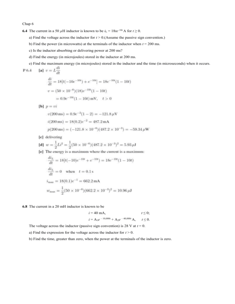
Chap 6 6.4 The current in a 50 µH inductor is known to be iL = 18te–10t A for t ≥ 0. a) Find the voltage across the inductor for t > 0.(Assume the passive sign convention.) b) Find the power (in microwatts) at the terminals of the inductor when t = 200 ms. c) Is the inductor absorbing or delivering power at 200 ms? d) Find the energy (in microjoules) stored in the inductor at 200 ms. e) Find the maximum energy (in microjoules) stored in the inductor and the time (in microseconds) when it occurs. 6.8 The current in a 20 mH inductor is known to be t ≤ 0; i = 40 mA, i = A1e – 10,000t + A2e – 40,000t A, t ≤ 0. The voltage across the inductor (passive sign convention) is 28 V at t = 0. a) Find the expression for the voltage across the inductor for t > 0. b) Find the time, greater than zero, when the power at the terminals of the inductor is zero. 6.19 The voltage across the terminals of a 0.25 µF capacitor is t 0; 50V, 4000t 4000 t A2e V, t 0. A1te The initial current in the capacitor is 400 mA. Assume the passive sign convention. a) What is the initial energy stored in the capacitor? b) Evaluate the coefficients A1 and A2. c) What is the expression for the capacitor current? 6.21 Assume that the initial energy stored in the inductors of Fig. P6.21 is zero. Find the equivalent inductance with respect to the terminals a ,b. Figure P6.21 6.23 The three inductors in the circuit in Fig. P6.23 are connected across the terminals of a black box at t = 0. The resulting voltage for t > 0 is known to be υ0 = 160e–4t V. If i1(0) = 1 A and i2(0) = 3 A, find a) io (0); b) io (t), t ≥ 0; c) i1 (t), t ≥ 0; d) i2 (t), t ≥ 0; e) the initial energy stored in the three inductors; f) the total energy delivered to the black box; and g) the energy trapped in the ideal inductors. Figure P6.23 6.26 Find the equivalent capacitance with respect to the terminals a, b for the circuit shown in Fig. P6.26. Figure P6.26 6.27 The two series-connected capacitors in Fig. P6.27 are connected to the terminals of a black box at t = 0. The resulting current i(t) for t > 0 is known to be 20e–t μA. a) Replace the original capacitors with an equivalent capacitor and find υo(t) for t ≥ 0. b) Find υ1(t) for t ≥ 0. c) Find υ2(t) for t ≥ 0. d) How much energy is delivered to the black box in the time interval 0 ≤ t ≤ ∞? e) How much energy was initially stored in the series capacitors? f) How much energy is trapped in the ideal capacitors? g) Do the solutions for υ1 and υ2 agree with the answer obtained in (f)? Figure P6.27 6.28 The three capacitors in the circuit in Fig. P6.28 are connected across the terminals of a black box at t = 0. The resulting current io for t > 0 is known to be io = 1.92e–20t mA. If υo(0) = –5 V and υ1(0) = 25 V, find the following for t ≥ 0: (a) υ2(t), (b) υ0(t), (c) υ1(t), (d) i1(t), and (e) i2(t). Figure P6.28 6.34 There is no energy stored in the circuit in Fig. P6.34 at the time the switch is opened. a) Derive the differential equation that governs the behavior of i2 if L1 = 4 H, L2 = 16 H, M = 2 H, and R0 = 32Ω. b) Show that when ig = 8 – 8e–t A, t ≥ 0, the differential equation derived in (a) is satisfied when i2 = e–t – e–2t A, t ≥ 0. c) Find the expression for the voltage υ1 across the current source. d) What is the initial value of υ1? Does this make sense in terms of known circuit behavior? Figure P6.34 6.46 a) Show that the two magnetically coupled coils in Fig. P6.46. can be replaced by a single coil having an inductance of Lab L1 L2 M 2 . L1 L2 2 M (Hint: Let i1 and i2 be clockwise mesh currents in the left and right “windows” of Fig. P6.46, respectively. Sum the voltages around the two meshes. In mesh 1 let υab be the unspecified applied voltage. Solve for di1/dt as a function of υab.) b) Show that if the if the magnetic polarity of coil 2 is reversed, then Lab L1 L2 M 2 L1 L2 2 M . Figure P6.46


![• [A] WO 9853550 A1 19981126 - MUNK NIELSEN STIG [DK] • [ID](http://s3.studylib.net/store/data/008241369_1-754aeea07c3d8e9488bccb33bdba5023-300x300.png)
