Control Systems: Polar & Bode Plot Tutorial
advertisement

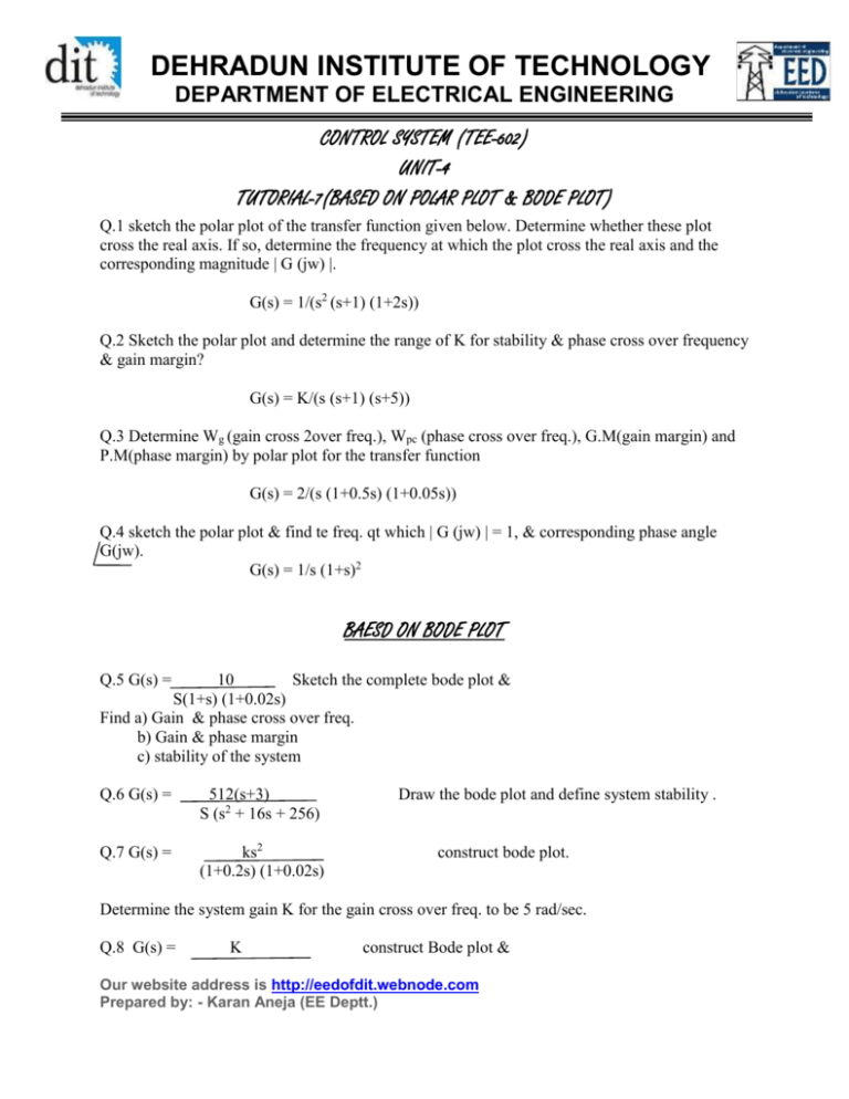
DEHRADUN INSTITUTE OF TECHNOLOGY DEPARTMENT OF ELECTRICAL ENGINEERING CONTROL SYSTEM (TEE-602) UNIT-4 TUTORIAL-7(BASED ON POLAR PLOT & BODE PLOT) Q.1 sketch the polar plot of the transfer function given below. Determine whether these plot cross the real axis. If so, determine the frequency at which the plot cross the real axis and the corresponding magnitude | G (jw) |. G(s) = 1/(s2 (s+1) (1+2s)) Q.2 Sketch the polar plot and determine the range of K for stability & phase cross over frequency & gain margin? G(s) = K/(s (s+1) (s+5)) Q.3 Determine Wg (gain cross 2over freq.), Wpc (phase cross over freq.), G.M(gain margin) and P.M(phase margin) by polar plot for the transfer function G(s) = 2/(s (1+0.5s) (1+0.05s)) Q.4 sketch the polar plot & find te freq. qt which | G (jw) | = 1, & corresponding phase angle G(jw). G(s) = 1/s (1+s)2 BAESD ON BODE PLOT Q.5 G(s) = 10 Sketch the complete bode plot & S(1+s) (1+0.02s) Find a) Gain & phase cross over freq. b) Gain & phase margin c) stability of the system Q.6 G(s) = 512(s+3) S (s2 + 16s + 256) Q.7 G(s) = ks2 (1+0.2s) (1+0.02s) Draw the bode plot and define system stability . construct bode plot. Determine the system gain K for the gain cross over freq. to be 5 rad/sec. Q.8 G(s) = K construct Bode plot & Our website address is http://eedofdit.webnode.com Prepared by: - Karan Aneja (EE Deptt.) DEHRADUN INSTITUTE OF TECHNOLOGY DEPARTMENT OF ELECTRICAL ENGINEERING S (s+2) (s+10) a) Find limiting value of K for system to be stable b) Value of K for gain margin to be 10 db c) Value of k for phase margin to be 50o Q.9 Figure 9 shows a Bode diagram, plot the transfer function. Fig 9 Q. 10 determine the transfer function for the bode diagram shown in fig. 10. Fig 10 Q. 11 the asymptotic approximation of gain plot is given in fig. 11. Determine its open loop transfer function? Our website address is http://eedofdit.webnode.com Prepared by: - Karan Aneja (EE Deptt.) DEHRADUN INSTITUTE OF TECHNOLOGY DEPARTMENT OF ELECTRICAL ENGINEERING Q.12 derive the transfer function of the system from the data given on the bode diagram shown in fig. 12 below. Our website address is http://eedofdit.webnode.com Prepared by: - Karan Aneja (EE Deptt.)


