Relay and Buzzer - Student Worksheet
advertisement

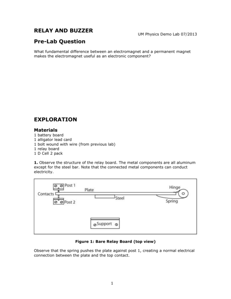
RELAY AND BUZZER UM Physics Demo Lab 07/2013 Pre-Lab Question What fundamental difference between an electromagnet and a permanent magnet makes the electromagnet useful as an electronic component? EXPLORATION Materials 1 1 1 1 1 battery board alligator lead card bolt wound with wire (from previous lab) relay board D Cell 2 pack 1. Observe the structure of the relay board. The metal components are all aluminum except for the steel bar. Note that the connected metal components can conduct electricity. Figure 1: Bare Relay Board (top view) Observe that the spring pushes the plate against post 1, creating a normal electrical connection between the plate and the top contact. 1 If a magnet is attached to the large support on the board, then it would attract the steel (just like a paper-clip). If the magnet is strong enough, then the plate will swing and connect with the bottom contact, overcoming the tension of the spring. There are two competing forces, the magnetic field and the spring. If there is no magnetic field, then the spring pushes the plate against post 1. If there is a sufficiently strong magnetic field, then the plate swings and connects with post 2. If an electromagnet is used, then the connection can be controlled with a switch. Build the circuit drawn below to control the hinged plate’s connections with the momentary contact switch. Use the bolt wound with wire your group built in the previous lab. Figure 2: Wired Relay Board Attach the bolt to the relay board with the two free-spinning nuts. Adjust the two nuts until the bolt is almost touching the hinged plate. Use the prototype in the front of the classroom for guidance if needed. 2. Press and release the momentary contact switch. Describe what happens. 2 3. Connect the relay board to a light and two cells wired in series for 3 V on the battery board. Figure 3: Relay Board with light Notice that the 6 V and 3 V circuits are completely independent of each other. 4. Press the momentary contact switch. Observe and describe what happens. 5. Draw a schematic diagram for the circuit you just built. Try to invent a new symbol for the coil that is wound around the bolt. This coil is called a solenoid. (Hint: make sure that you completely separate the two circuits.) 3 Challenge Work: Moving only one connection, change the board so the light goes out when you press the momentary contact switch. Doing so, you change the relay from normally-open to normally-closed. Draw the schematic for this new circuit and indicate what you changed compared to the schematic you drew for part 5. 4 Everyday Applications Old west style telegraph Remote switches Elevators Doorbells Car power locks and windows Car turn signals APPLICATION Materials 1 battery board 1 alligator lead card 1 relay board with bolt 1. Build the circuit as shown below. Figure 4: Lantern Battery With Relay Board 2. Press the momentary contact switch and observe what happens. 5 3. Explain how this buzzer works. 4. Draw a schematic diagram for the buzzer you just built. (Hint: make sure that you draw a single circuit now.) 6 5. Describe an everyday application for this kind of buzzer. Challenge Work: Which group can achieve the loudest buzzer? What variables can you change to make this happen? Note: Do not change or tweak the steel spring hinge! Describe what you did to your buzzer to accomplish this. Summary: 1. Electromagnets produce a magnetic field which can be switched on and off. This makes them useful for building a number of practical electronic devices 2. A relay is a magnetically activated switch. Relays are useful because a relatively small current in the coil circuit can be used to control a much larger current flowing in the circuit controlled by the contacts. They also make it possible for one circuit to control another without the two circuits being directly connected (electrical isolation). 3. A buzzer is a simple electro-mechanical oscillator using negative feedback. Feedback is defined as connecting all or part of the output signal from a circuit back to its input. Final Clean-up Please disconnect all alligator leads and reattach them to the clip card. Remove the bolt from the relay board and replace the board to the cart. You are done with the bolt--it will be disassembled for you. Replace the battery board to the cart. 7 Relays and Buzzers Relays A relay is an electrical switch that is composed of an electromagnet and a pivoting connector. The relay can be one of two types: normally open or normally closed. Normally open means that when the electromagnet is inactive (has no current and therefore no strong magnetic field) the switch is open. An open switch is not electrically connected, so no current can flow through the attached circuit. When the electromagnet is activated, the switch closes, completing the circuit. Normally closed means when the electromagnet is inactive the switch is closed, so the attached circuit is completed. When the electromagnet is activated, it opens the circuit. When the relay created its electrical connection, you heard a sound of the plate hitting the contact. Listening to the sounds from a relay just like you built is the essential technology that allowed incoming telegraph messages to be read in Morse code. Relays are widely used. Doorbells and elevators use normally open relays. When you press the button an electromagnet is powered and a switch is closed to activate the device. Some fuses are examples of normally closed relays. They allow current to flow, but when there is too much current they open the switch. Electromagnets and Permanent Magnets You’ve seen the application of electromagnets where a current creates a magnetic field. What about permanent magnets? It turns out on the atomic scale electrons themselves act as currents creating tiny magnetic fields. Normally, these fields are oriented randomly, but some materials these atomic currents can be aligned along a preferred direction. Those materials are permanent magnets. 8


