Annals of DAAAM for 2009 & Proceedings of 20th DAAAM
advertisement

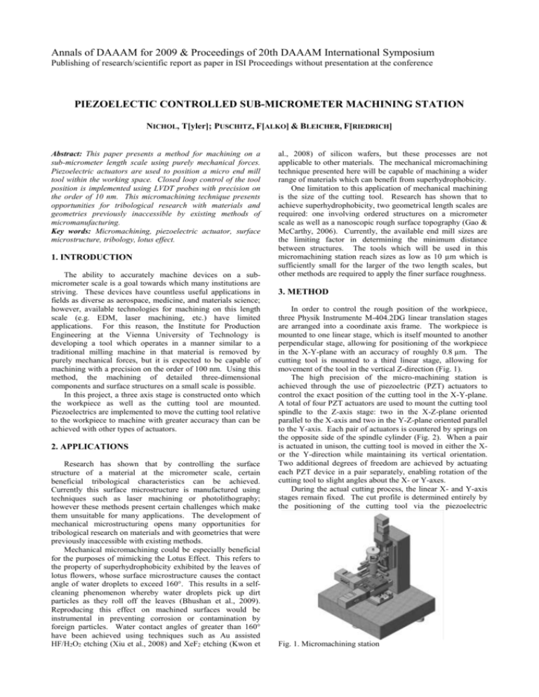
Annals of DAAAM for 2009 & Proceedings of 20th DAAAM International Symposium Publishing of research/scientific report as paper in ISI Proceedings without presentation at the conference PIEZOELECTIC CONTROLLED SUB-MICROMETER MACHINING STATION NICHOL, T[yler]; PUSCHITZ, F[ALKO] & BLEICHER, F[RIEDRICH] Abstract: This paper presents a method for machining on a sub-micrometer length scale using purely mechanical forces. Piezoelectric actuators are used to position a micro end mill tool within the working space. Closed loop control of the tool position is implemented using LVDT probes with precision on the order of 10 nm. This micromachining technique presents opportunities for tribological research with materials and geometries previously inaccessible by existing methods of micromanufacturing. Key words: Micromachining, piezoelectric actuator, surface microstructure, tribology, lotus effect. 1. INTRODUCTION The ability to accurately machine devices on a submicrometer scale is a goal towards which many institutions are striving. These devices have countless useful applications in fields as diverse as aerospace, medicine, and materials science; however, available technologies for machining on this length scale (e.g. EDM, laser machining, etc.) have limited applications. For this reason, the Institute for Production Engineering at the Vienna University of Technology is developing a tool which operates in a manner similar to a traditional milling machine in that material is removed by purely mechanical forces, but it is expected to be capable of machining with a precision on the order of 100 nm. Using this method, the machining of detailed three-dimensional components and surface structures on a small scale is possible. In this project, a three axis stage is constructed onto which the workpiece as well as the cutting tool are mounted. Piezoelectrics are implemented to move the cutting tool relative to the workpiece to machine with greater accuracy than can be achieved with other types of actuators. 2. APPLICATIONS Research has shown that by controlling the surface structure of a material at the micrometer scale, certain beneficial tribological characteristics can be achieved. Currently this surface microstructure is manufactured using techniques such as laser machining or photolithography; however these methods present certain challenges which make them unsuitable for many applications. The development of mechanical microstructuring opens many opportunities for tribological research on materials and with geometries that were previously inaccessible with existing methods. Mechanical micromachining could be especially beneficial for the purposes of mimicking the Lotus Effect. This refers to the property of superhydrophobicity exhibited by the leaves of lotus flowers, whose surface microstructure causes the contact angle of water droplets to exceed 160°. This results in a selfcleaning phenomenon whereby water droplets pick up dirt particles as they roll off the leaves (Bhushan et al., 2009). Reproducing this effect on machined surfaces would be instrumental in preventing corrosion or contamination by foreign particles. Water contact angles of greater than 160° have been achieved using techniques such as Au assisted HF/H2O2 etching (Xiu et al., 2008) and XeF2 etching (Kwon et al., 2008) of silicon wafers, but these processes are not applicable to other materials. The mechanical micromachining technique presented here will be capable of machining a wider range of materials which can benefit from superhydrophobicity. One limitation to this application of mechanical machining is the size of the cutting tool. Research has shown that to achieve superhydrophobicity, two geometrical length scales are required: one involving ordered structures on a micrometer scale as well as a nanoscopic rough surface topography (Gao & McCarthy, 2006). Currently, the available end mill sizes are the limiting factor in determining the minimum distance between structures. The tools which will be used in this micromachining station reach sizes as low as 10 µm which is sufficiently small for the larger of the two length scales, but other methods are required to apply the finer surface roughness. 3. METHOD In order to control the rough position of the workpiece, three Physik Instrumente M-404.2DG linear translation stages are arranged into a coordinate axis frame. The workpiece is mounted to one linear stage, which is itself mounted to another perpendicular stage, allowing for positioning of the workpiece in the X-Y-plane with an accuracy of roughly 0.8 µm. The cutting tool is mounted to a third linear stage, allowing for movement of the tool in the vertical Z-direction (Fig. 1). The high precision of the micro-machining station is achieved through the use of piezoelectric (PZT) actuators to control the exact position of the cutting tool in the X-Y-plane. A total of four PZT actuators are used to mount the cutting tool spindle to the Z-axis stage: two in the X-Z-plane oriented parallel to the X-axis and two in the Y-Z-plane oriented parallel to the Y-axis. Each pair of actuators is countered by springs on the opposite side of the spindle cylinder (Fig. 2). When a pair is actuated in unison, the cutting tool is moved in either the Xor the Y-direction while maintaining its vertical orientation. Two additional degrees of freedom are achieved by actuating each PZT device in a pair separately, enabling rotation of the cutting tool to slight angles about the X- or Y-axes. During the actual cutting process, the linear X- and Y-axis stages remain fixed. The cut profile is determined entirely by the positioning of the cutting tool via the piezoelectric Fig. 1. Micromachining station will be caused to deflect to an undesired location; however, this can be prevented using the LVDT probes. The distance sensors monitor the position of the spindle within its housing and, by extension, the tool center point. From this, the deviation of the tool with respect to the programmed cut path is calculated. If this deviation is found to increase past a maximum allowed value, the LabVIEW software adjusts the voltage being applied across the terminals of the piezos in order to reduce the deviation to an acceptable level. This ensures that the desired cut profile is followed with the greatest possible accuracy. 5. MATERIAL REQUIREMENTS Fig. 2. Cut view of spindle housing actuators, as well as the vertical motion of the Z-axis stage. The resolution of the tool position is in large part determined by the resolution of the output voltage of the computer controller hardware and the sensitivity of the piezo devices. The current configuration uses a 16-bit DAQ with an output range of zero to 10 V and a voltage output resolution of 0.153 mV. The output voltage is converted to an analog signal from zero to 120 V. Tests will be conducted to determine the sensitivity and, subsequently, the resolution of the deflection of the PZT actuators corresponding to the DAQ output. Closed-loop control is implemented using sensors capable of resolution on the order of 10 nm to ensure the greatest precision is achieved. This control strategy is discussed in the following section. The cutting tool is fixed to a high speed precision pneumatic spindle which is capable of reaching up to 65000 RPM. Since the cutting tool itself can reach sizes as small as 10 µm in diameter, the high angular velocity of the pneumatic spindle is required to achieve appropriate cutting speeds. The PZT actuators are capable of a maximum deflection of 50 µm, therefore the cutting area in the X-Y-plane for a single machining step is limited to an area of 50x50 µm. Given the size of the cutting tool, this is not sufficient to machine useful devices or surface structures; however, the successful execution of this machining station is the first step toward the design of larger machines with similar tolerance capabilities. 4. CONTROL STRATEGIES For the purposes of experimentation, a program was written using the LabVIEW virtual instrument software. The three linear stages are controlled using virtual instruments (VIs) provided by Physik Instrumente which were specifically designed for integration into the LabVIEW environment. These VIs are capable of controlling the position, velocity, acceleration, and other characteristics of the linear stages. The piezoelectric actuators are controlled in the same principle VI as the linear stages, allowing for seamless integration of both control steps. The piezos are controlled using the measured sensitivity of deflection to DAQ output voltage for each piezo device. The user inputs the desired cut dimensions and the program calculates the required voltage that must be applied across the terminals of each PZT device to achieve the necessary deflection. For more complicated cut profiles such as curves, the LabVIEW program takes a path dictated by the user and determines four functions of voltage with respect to time, one for each piezoelectric actuator, which when executed simultaneously achieve the desired cut profile. In this way, the micromachining station is able to operate as a fully automated NC-machine capable of machining sophisticated patterns quickly and accurately. Closed-loop control is implemented using four highly accurate ductile length measuring LVDT probes. The probes are capable of resolution as high as 10 nm and are positioned near each piezoelectric actuator. The high resolution of the probes is useful for controlling the deflection of each piezo. If the voltage applied across a piezo device is too great, the piezo Due to the small size of the cutting tool, materials must exhibit certain properties in order to take full advantage of the high precision machining capabilities. Materials with large grain sizes will have difficulty in this machine due to the increased stiffness of the material during cutting. This subjects the end mill to greater forces, which cause greater deformation of the end mill as well as increased tool wear. For this reason, the performance of the micro-machining station will be tested using special aluminum stock, which is first passed through the equal-channel angular extrusion process developed by the Chemnitz University of Technology, in which a bar of aluminum stock is forced through a channel with a 90 degree bend. The large strain to which the aluminum is subjected as a result of being passed through the angled channel causes a reduction of the grain size to the ultrafine grain region between 100 nm and a few micrometers (Hockauf et al., 2008). 6. CONCLUSION The Institute for Production Engineering is developing a mechanical machining station with sub-micrometer precision. The tool is controlled using piezoelectric actuators and ductile position sensors to enable closed-loop control on the order of 100 nm. This tool can serve functions in the field of tribological research as well as any industry where micro-scale components are used. Testing still needs to be conducted in order to determine the exact tolerances to which the device can machine with various materials. This small scale machining station is the first step in the design of machines with a larger working area and similar tolerance capabilities. 7. REFERENCES Bhushan, B.; Jung, Y. C. & Kock, K. (2009). Micro-, Nanoand Hierarchical Structures for Superhydrophobicity, SelfCleaning and Low Adhesion. Philosophical Transactions of the Royal Society A, 367, 1894, May 2009, 1631-1672, ISSN: 1364503X Gao, L. & McCarthy, T. (2006). The Lotus Effect Explained: Two Reasons Why Two Length Scales of Topography Are Important. Langmuir, 22, 7, March 2006, pp. 2966-2977, ISSN: 07437463 Hockauf, M.; Meyer, L.W.; Nickel, D.; Alisch, G.; Lampke, T.; Wielage, B. & Krüger, L. (2008). Mechanical properties and corrosion behaviour of ultrafine-grained AA6082 produced by equal-channel angular pressing. Journal of Materials Science, 43, 23-24, December 2008, pp. 74097417, ISSN: 00222461 Kwon, Y.; Patankar, N.; Choi, J. & Lee, J. (2008). Design of Surface Hierarchy for Extreme Hydrophobicity, Langmuir, 25, 11, February 2009, pp. 6129–6136, ISSN: 07437463 Xiu, Y.; Hess, D. W. & Wong, C. P. (2008). Hierarchically Etched Silicon Lotus Effect Surface Structures for Reduced Light Reflection, Proceedings of Electronics Packaging Technology Conference, pp. 916-922, ISBN: 9781424421176, Singapore, December 2008, IEEE, Los Alamitos CA


