State/Output Table
advertisement
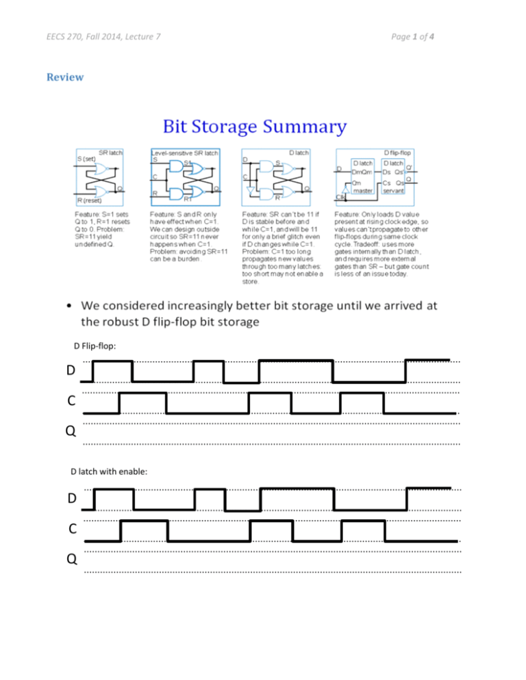
EECS 270, Fall 2014, Lecture 7 Review D Flip-flop: D C Q D latch with enable: D C Q Page 1 of 4 EECS 270, Fall 2014, Lecture 7 Page 2 of 4 Finite State Machines (sections 3.3 & 3.4) We’ve touched on designing state transition diagrams. Let’s now focus on the mechanical process of going from a state-transition diagram to a gate-level implementation of the state machine (and then go the other way!) A simple example: State assignment: State Bob X=1 Tom X=0 !a Q1 Q0 0 0 0 1 1 0 1 1 a !a a Mary X=1 Fill in the table, and then draw the devices! State/Output Table: Current State Input a=0 a=1 Output X State/Output Table (Different format) Inputs Q1 Q0 0 0 0 0 0 1 0 1 1 0 1 0 1 1 1 1 a 0 1 0 1 0 1 0 1 Outputs D1 D0 X EECS 270, Fall 2014, Lecture 7 Page 3 of 4 FSM Design – One more That problem is a bit more complex than works well for a simple example, so let’s go with: Design a state transition diagram (the lines and circles) which solves the following problem. There is one input, X, and one output, A. A is high if the last 3 inputs on X were 101. X: 11101011010001111010 A: 00000101001000000001 As before, the output is going high _after_ the input pattern occurs due to the delay inherent in a Moore machine. State Transition Diagram: (How many flip-flops are needed?) State/Output Table: Current State Input X=0 X=1 Output A State assignment: State Q1 Q0 0 0 0 1 1 0 1 1 State table in a different format Q1 Q0 X D1 D0 0 0 0 0 0 1 0 1 0 0 1 1 1 0 0 1 0 1 1 1 0 1 1 1 EECS 270, Fall 2014, Lecture 7 Q1 Q0 X D1 D0 0 0 0 0 0 1 0 1 0 0 1 1 1 0 0 1 0 1 1 1 0 1 1 1 D1=____________________________________________ D2=____________________________________________ A=_____________________________________________ Where do each of those things go in the above architecture? Draw the circuit: Page 4 of 4
