Euler Angles
advertisement
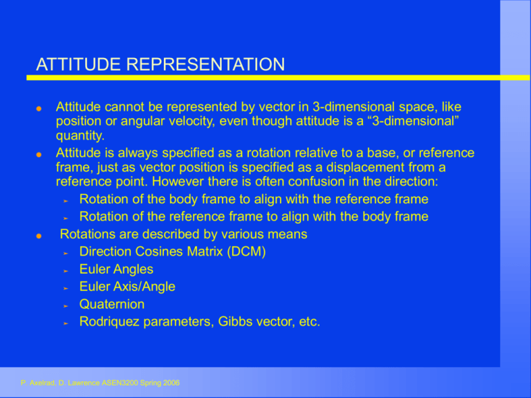
ATTITUDE REPRESENTATION Attitude cannot be represented by vector in 3-dimensional space, like position or angular velocity, even though attitude is a “3-dimensional” quantity. Attitude is always specified as a rotation relative to a base, or reference frame, just as vector position is specified as a displacement from a reference point. However there is often confusion in the direction: Rotation of the body frame to align with the reference frame Rotation of the reference frame to align with the body frame Rotations are described by various means Direction Cosines Matrix (DCM) Euler Angles Euler Axis/Angle Quaternion Rodriquez parameters, Gibbs vector, etc. P. Axelrad, D. Lawrence ASEN3200 Spring 2006 DIRECTION COSINES MATRIX The DCM transforms a vector representation from one coordinate frame to another, or rotates vectors from one attitude to another. r B r2 A R 2 r1 A 1 The DCM can be formed by dot products of unit vectors of two frames T B A T B r A or A iB iA jB i A k B iA iB j A iB k A jB k A or k B k A i2 i1 1 jB j A R 2 i2 j1 i2 k1 kB jA A 1 T Note that if we set A=1 and B=2, T R B 2 j2 i1 j2 j1 j2 k1 k2 i1 k 2 j1 k2 k1 The nine elements are not independent because the DCM must be orthonormal T B T A T A T B A P. Axelrad, D. Lawrence ASEN3200 Spring 2006 B B A =I EULER ANGLES Euler Angles are a particular sequence of three rotations about particular reference frame axes. Both the sequence and the axes must be specified to clearly define the attitude (rotation) of interest. The same angle values used in a different sequence, or about different axes, results in a different attitude Example: Yaw-Pitch-Roll Euler angle sequence rotating the reference frame (call it frame 1) into the body frame: 1) - Yaw the reference frame about its k-axis with angle y to produce the 2-frame 2) - Pitch about the new j-axis with angle to produce the 3-frame 3) - Roll about the new i-axis with angle to produce the body frame B The resulting rotation matrix rotating 1-frame vectors v into their corresponding body frame position is given by vB 1 = R B v1 1 1 where P. Axelrad, D. Lawrence ASEN3200 Spring 2006 R B R( )B R( )3 R(y )2 1 3 2 1 EULER ANGLE EXAMPLE Yaw,Pitch,Roll (k,j,i) Sequence i3 Reference Frame is Frame 1 pitch i1 j2 j1 yaw i2 j2,j3 i2 k1,k2 k2 i3,iB Rotate about k1 (angle y k3 Rotate about j2 (angle roll Rotate about i3 j3 (angle Body frame is Frame B jB k3 kB DCMs FOR GENERAL EULER ROTATIONS 1 1 R 2 0 0 0 c s i 1 j 2 k 0 s c c 1 R 2 0 s c 1 R 2 s 0 P. Axelrad, D. Lawrence ASEN3200 Spring 2006 2 i 0 1 0 s c 0 s 0 c 1 j 0 j 0 1 k i 1 2 k Transformation Matrix for Euler Yaw,Pitch,Roll (k,j,i) c cy 1 R321 y , , B c sy s s cy s sy c s cy P. Axelrad, D. Lawrence ASEN3200 Spring 2006 c sy c cy s s sy s cy c s sy s s c c c EULER’S THEOREM (EULER AXIS/ANGLE REP.) Any rigid body rotation can be expressed by a single rotation about a fixed axis. The rotation matrix [R] is given in terms of a unit vector along the “Euler axis” e (a unit vector), and the angle, R n, 2 cos I + 1-cos e1 e1 sin [[e]1 ] 1 T cos 1 2 tr R 1 1 e 2 R23 R32 1 R31 R13 e1 2sin R12 R21 Shuster, M., "Survey of Attitude Representations," Journal of Astronautical Sciences, Vol. 41, No. 4, Oct.-Dec. 1993. pp. 439-517. P. Axelrad, D. Lawrence ASEN3200 Spring 2006 NOTATION r b r B b r1b1 r2b2 r3b3 T Vector Dot Product B Vector Cross Product r b [[b ]B ] r B B Cross Product Matrix for vector 0 [[b ]B ] b3 b2 c = cos() s = sin() P. Axelrad, D. Lawrence ASEN3200 Spring 2006 b3 0 b1 b2 b1 0 where b B b1 b2 b3 QUATERNION REPRESENTATION OF ATTITUDE Only one redundant element requiring use of a constraint | q | = 1 Only ambiguity is a sign Can be combined easily to produce successive rotations DCM computation given by multiply & add of quaternion elements (no trig functions) Propagation requires integration of only 4 kinematic equations Widely used because of simplicity of operations and small dimension, together with lack of representation singularity q1 q2 q q3 q4 Shuster, M., "Survey of Attitude Representations," Journal of the Astronautical Sciences, Vol. 41, No. 4, Oct.-Dec. 1993. pp. 439-517. P. Axelrad, D. Lawrence ASEN3200 Spring 2006 QUATERNION REPRESENTATION Given Euler Axis e and angle q1 q1 q2 q q2 sin e, q4 cos , q 2 2 q3 q3 q4 q q4 1 (q must be constrained to unit length) 2 2 P. Axelrad, D. Lawrence ASEN3200 Spring 2006 Quaternion versus Rotation Matrix (DCM_ R(q , q4 ) q4 q 2 2 I 2 q q T 2q4 [[q ]] q12 q2 2 q32 q4 2 R (q ) 2 q1q2 q4 q3 2 q3 q1 q4 q2 2 q1q2 q4 q3 q1 q2 q3 q4 2 2 2 2 q3 q2 q4 q1 2 q1q3 q4 q2 2 2 q2 q3 q4 q1 2 2 2 2 q1 q2 q3 q4 1 1 trR , 2 1 1 1 q1 R R , q R R , q 23 32 2 31 13 3 R12 R21 4q4 4q4 4q4 trR 4q4 1, q4 2 P. Axelrad, D. Lawrence ASEN3200 Spring 2006 Quaternion Composition (Successive Rotations) RCA RCB RBA q3 C q2 C q1 B A A B q3 C q1 B q2 C A B q4 q3 q q2 q1 P. Axelrad, D. Lawrence ASEN3200 Spring 2006 A (Note the swapped order) q3 q2 q4 q1 q1 q4 q2 q3 q1 q2 q3 q4 Kinematics Relationship between angular velocity and attitude representations d R (t ) dt = R(t ) [[ t ]] q4 (t ) d q (t ) 1 q3 (t ) = dt 2 q2 (t ) q1 (t ) P. Axelrad, D. Lawrence ASEN3200 Spring 2006 q3 (t ) q4 (t ) q1 (t ) q2 (t ) q2 (t ) 1 (t ) q1 (t ) 2 (t ) q4 (t ) 3 (t ) q3 (t ) SMALL ANGLE APPROXIMATIONS For a small angles , sin( ~ , cos( ~ 1 The rotation DCM for a sequence of three small Euler angles is: 1 R I [[ ]] 3 2 P. Axelrad, D. Lawrence ASEN3200 Spring 2006 3 1 1 2 1 1 ATTITUDE DETERMINATION PROBLEM Use standard attitude sensors such as a star tracker or sun sensor Sensor axes are calibrated with respect to body-fixed reference frame (B) Direction to reference object (sun or star) is found in an inertial frame (I) using star catalog, ephemeris prediction, etc. Direction to reference object is also measured by the on-board sensors and expressed in the (B) frame. Now have one or more unit vectors to objects expressed in both (I) and in (B). Note that a minimum of 2 “independent” objects is required to determine 3-D attitude Calculate the attitude DCM P. Axelrad, D. Lawrence ASEN3200 Spring 2006 ATTITUDE DETERMINATION PROBLEM Given measurements of two unit vectors (pointing to two objects) in a body frame and a reference frame v1 A , v1 B , v2 A , v2 B How can the DCM representing attitude be determined? T must simultaneously satisfy v1 B T B v1 A A and v2 B T B v2 A A Deterministic method - TRIAD Use two of the measured vectors to define a set of three orthogonal unit vectors in the two frames. Create a matrix equation from the three vector equations and use this to solve for the attitude DCM P. Axelrad, D. Lawrence ASEN3200 Spring 2006 DETERMINISTIC ATTITUDE DETERMINATION Given unit vectors Construct v1 A , v1 B , v2 A , v2 B v1 A v2 A r1 v1 A , r2 , r3 r1 r2 v1 A v2 A v1 B v2 B s1 v1 B , s2 , s3 s1 s2 v1 B v2 B M R r1 r2 r3 M s s1 s2 s3 T B M s M RT A P. Axelrad, D. Lawrence ASEN3200 Spring 2006 Transformation DCM estimate (note rotation DCM R A is the B transpose of this) Attitude Representations and Attitude Determination REFERENCES Shuster, M., "Survey of Attitude Representations," Journal of the Astronautical Sciences, Vol. 41, No. 4, Oct.-Dec. 1993. pp. 439-517. Shuster, M. D. and Oh, S. D., "Three-Axis Attitude Determination from Vector Observations," Journal of Guidance and Control, Vol. 4, No. 1, Jan.-Feb. 1981, pp. 70-77. Wertz, J. R., ed. Spacecraft Attitude Determination and Control, Kluwer Academic Publishers, Dordrecht, Netherlands, 1978. P. Axelrad, D. Lawrence ASEN3200 Spring 2006

