File - dmel framework
advertisement
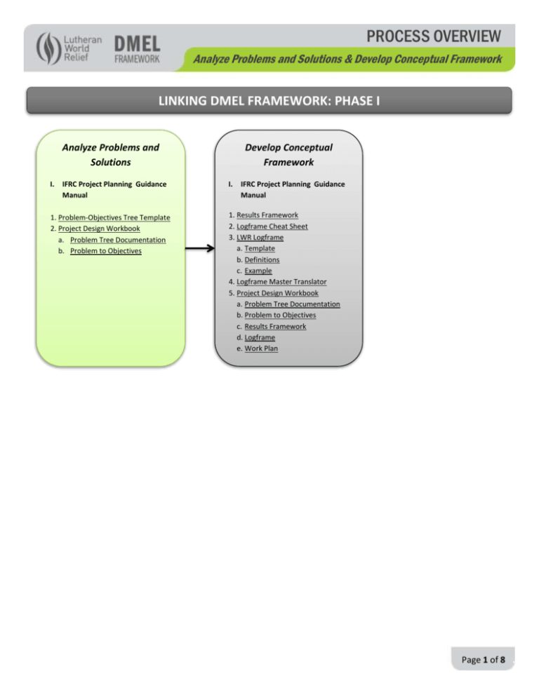
PROCESS OVERVIEW Analyze Problems and Solutions & Develop Conceptual Framework LINKING DMEL FRAMEWORK: PHASE I Develop Conceptual Framework Analyze Problems and Solutions I. IFRC Project Planning Guidance Manual 1. Problem-Objectives Tree Template 2. Project Design Workbook a. Problem Tree Documentation b. Problem to Objectives I. IFRC Project Planning Guidance Manual 1. Results Framework 2. Logframe Cheat Sheet 3. LWR Logframe a. Template b. Definitions c. Example 4. Logframe Master Translator 5. Project Design Workbook a. Problem Tree Documentation b. Problem to Objectives c. Results Framework d. Logframe e. Work Plan Page 1 of 8 . PROCESS OVERVIEW Analyze Problems and Solutions & Develop Conceptual Framework 1. INTRODUCTION Project Cycle Stage Process Analyze problems and solutions Guide – Manual I. IFRC Project Planning Guidance Manual I. IFRC Project Planning Guidance Manual INITIATING Develop conceptual framework Tools 1. Problem-Objectives Tree Template 2. Project Design Workbook a. Problem Analysis Documentation b. Problem to Objectives 1. Results Framework 2. Logframe Cheat Sheet 3. Logframe a. Template b. Definitions c. Example 4. Logframe Master Translator 5. Project Design Workbook a. Problem Analysis Documentation b. Problem to Objectives c. Results Framework d. Logframe e. Work Plan Additional Resources A. LWR Grants Acquisition Manual B. CRS Problem Tree Guidance A. LWR Grants Acquisition Manual B. USAID Tips: BUILDING A RESULTS FRAMEWORK PROCESSES AND THE PROJECT CYCLE: The INITIATING Stage in the DMEL Framework covers three processes. Two of the three processes of INITIATING are covered in this Process Overview: Analyze problems and solutions and Develop conceptual framework. The third process, Develop initial M&E plan, is also part of INITIATION but is covered in the Process Overview for M&E planning as it is closely linked to the PLANNING process of Create detailed M&E plan. The tools used to complete these two processes can be viewed as the bricks that form the foundation of a quality project design. The cause and effect logic used in the tools can be viewed as the mortar between the bricks that holds the foundation together. A weak foundation of a house creates weaknesses throughout the rest of the house. This is the same as in project design. If a project is built on top of a weak foundation, the rest of the project will experience weaknesses that will ultimately lessen the project’s ability to achieve its expected impact. HELPING US IN OUR WORK Although all processes involved in M&E are important, completing these two processes creates the foundation of the entire project. Clearly understanding the problem, with help from all project stakeholders, ensures that the chosen design meets participants’ needs and desires and takes into account the unique context in which the project will be implemented. Ensuring that the each objective is linked to a verifiable problem or cause ensures that we select the most appropriate project design Page 2 of 8 . PROCESS OVERVIEW Analyze Problems and Solutions & Develop Conceptual Framework o It helps ensure that activities are not selected just because they worked in a similar context in the past. Each project context is unique and a thorough analysis of the need/situation should be conducted, even if just to reaffirm what is already known. Thinking through the value of collecting each indicator and how the data will help the project and LWR accomplish its goals will help reduce the number of indicators. Streamlined indictors will reduce the amount of time and work spent on collecting data that does not have a clear use. Understanding and properly applying the DMEL tools for these processes cuts down on time needed for revisions and adjustments to project proposals Knowing donor requirements in advance increases the probability of winning the grant, which also decreases time spent on unsuccessful proposals. PROCESS GUIDE – MANUAL: The key resource for detailed guidance on each of these processes is the IFRC Project Planning Guidance Manual. The aim of the guidance manual is to introduce the user to project initiation and planning. It describes the different stages (INITIATION and PLANNING) of the “project cycle” within the context of Results-Based Management (RBM). It also gives an overview of the various components of RBM and explains how to integrate and apply this approach in practice. In addition, the manual briefly summarizes the other key phases of the cycle (assessment, implementation and monitoring, evaluation).1 It is recommended that all LWR staff read the entire IFRC Project Planning Guidance Manual to orient themselves on how the content is presented and flows from conducting the problem analysis to the completion of the logframe. The manual is particularly useful for LWR staff and partner staff who have little background in project design and planning. It is clear, concise, and of comparatively short length. o For those staff that has a more detailed knowledge of project design and planning, the manual can be used as simple reference. To assist in using the document as a reference, each process outlined in this document is linked to specific sections of the manual in the Tables 2.1 and 3.1. Given that the manual was developed for the IFRC there is some IFRC specific language and examples. Nevertheless, the overall content is general and reflects the most commonly used terms and methodologies by INGOs. o The terms used in the manual, in particular in the logframe, have become LWR standards and are used consistently in the rest of the DMEL Framework. 2. PROCESS: ANALYZE PROBLEMS AND SOLUTIONS Table 2.1 DESCRIPTION: TOOLS - ADDITIONAL RESOURCES This table gives a brief description of each tool and additional resource for the process of Analyze problems and solutions. The description can be used in conjunction with Table 2.2 to help identify which tool to use for your specific M&E need. TOOLS 1. Problem Tree & Objectives Tree Template: This tool contains instructions and blank templates that can be used to organize the information resulting from the use of the Problem Tree method and the Objective Tree method. The blank templates are in Word format. The Word template provided is a typical graphical presentation of a problem 1 IFRC (International Federation of the Red Cross and Red Crescent Societies). 2010. Project/ Program Planning Guidance Manual. Geneva Page 3 of 8 . PROCESS OVERVIEW Analyze Problems and Solutions & Develop Conceptual Framework tree. The graphic can be manipulated (size and number of boxes) to reflect the results of the Problem Tree analysis, which is often completed with sticky notes and a flip chart. If the Word template is used it must be transferred to the Project Design Workbook once completed. To do so, copy the whole graphic and paste it into the Project Design Workbook using the “Paste Special” function and paste it as a “Picture (PNG)” Use the Problem to Objectives tab of the Project Design Workbook to document all the possible solutions (Goal, Outcomes, Outputs) to the problem and causes identified during the Problem Tree analysis. Use the Objective Tree Method to determine the final solution identified by the project. The Results Framework tab will document the final solution that is chosen. IMPORTANT: Any method or program can be used to document the results of the Problem Tree in the Project Design Workbook. What is important is that the results are documented. Problem Tree: The Problem Tree is a method for conducting a problem analysis. The aim of problem tree is to structure, summarize and organize the initial findings of an assessment in order to arrive at a clearer understanding of the situation under analysis. It is the visual representation of the results of the problem analysis. This visual method uses the analogy of a tree to facilitate the analysis of the problem(s). The exercise produces a summary picture of the existing negative situation, for example with the main problem as the “trunk”, the causes of the problem as the “roots” and the effects of the problem as the “branches”. Objectives Tree: Is the visual representation of the results from an objectives analysis. The objectives analysis clarifies the “means and ends” relationship between the desirable situation that would be attained, and the solutions for attaining it. The negative statements of each level of the Problem Tree are turned into positive statements and become the expected results of the project. Causes become outputs and outcomes while the problem statement is turned into the project’s goal. 2. Project Design Book: The purpose of the Project Design Book is to document and show the links among all the different parts of the project design including: a. Problem Tree Documentation b. Problems to Objectives c. Results Framework d. Logframe e. Work Plan The Project Design Workbook is contained in two files. 1. Project Design Workbook Instructions: Contains tabs with instructions as well as the templates. The instructions can be used to ensure that each tab (a-e above) is filled out correctly. 2. Project Design Workbook Blank Template: Does not contain instructions, only the blank templates. This is the final design document for the project. DO NOT use the INSTRUCTION file as the final draft of the Project Design Workbook. ADDITIONAL RESOURCES A. LWR Grants Acquisition Manual: This manual provides guidance on roles and procedures used by the New Business Page 4 of 8 . PROCESS OVERVIEW Analyze Problems and Solutions & Develop Conceptual Framework Development Unit to complete the project design for restricted proposals above $500,000. B. CRS Problem Tree Guidance2: This guidance provides more details on how to construct a Problem Tree using the Problem Tree methodology. This is a supplementary resource to the description of the Problem Tree methodology provided in the IFRC Project Planning Guidance Manual. PROCESS AIM: The aim of this process is to structure, summarize and organize the initial findings of the needs assessment in order to arrive at a clearer understanding of the situation under analysis and begin to outline the project’s expected results through the creation of its objective statements. PROCESS DEFINED: Analyze problems and solutions The problem analysis is defined as the thorough study of one or more problems (identified during the assessment stage), to identify their causes and decide whether and how to solve them. It involves identifying the negative aspects of an existing situation (i.e. “problems”) and then identifying the immediate and underlying causes. By identifying the causes of a problem, it is possible to start to identify possible solutions through the creation of project objectives. Analyzing the problem is a critical aspect of project planning, as it guides all subsequent analysis and decisionmaking on priorities. Merely listing and ranking problems does not provide for a sufficiently deep analysis of the situation. The Objectives Tree analysis is a key step that comes between the Problem Tree analysis and the completion of the project’s Results Framework. GOOD PRACTICE FOR GREAT RESULTS: This section is to document best practices. This section will be continually updated to reflect any best practices encountered throughout LWR’s programming worldwide. Table 2.2 PROCESS STEPS AND RESOURCES Below you will find summary steps involved in the process of Identify problems and solutions. It should be noted that these steps are not exhaustive and seek only to guide the user to the relevant sections within the guide-manual and the specific tools that are used to complete the entire process. The second column in this table shows the exact location of the sections of the IFRC Project Planning Guidance Manual that explain the step and has general guidance on the tools outlined in the third column. Each tool listed in the third column has guidance at the beginning of the document that covers the following aspects of the tool: purpose, information sources, who, when, recommendations, tips. Step Guide-Manual Location Tools 1. Conduct a problem analysis using 4.1.4: Problem analysis using the 1. Problem Tree-Objectives Tree the Problem Tree methodology “problem tree” tool (P. 21-22) Template Annex 1: How to create a B. CRS Problem Tree Guidance problem tree (P. 51-53) 2. Ensure that each problem/cause that is identified in the problem analysis is linked to evidence that N/A 2. Project Design Workbook b. Problems to Objectives 2 Stetson, V., Sharrock, G., Hahn, S. 2004. “ProPak: The CRS Project Package: Project Design and Proposal Guidance for Project and Program Managers.” Catholic Relief Services, Baltimore, MD. Page 5 of 8 . PROCESS OVERVIEW Analyze Problems and Solutions & Develop Conceptual Framework it actually exists. This will avoid identifying problems/causes that are not actually present in the target population. 3. Begin initial development of objectives through the creation of an objectives tree using the problem tree as a direct reference. 4. Assess the set of solutions identified in the objectives tree and choose among the different options available the most appropriate solutions given the resources available and any constraints present. 4.2 Development of objectives (P. 22-24) Annex 2: How to create and use an objectives tree (P. 54-56) 4.3.1 Suggested method for analysis (P. 25-26) Annex 2: How to create and use an objectives tree (P. 54-56) 1. Problem Tree-Objectives Tree Template 2. Project Design Workbook b. Problems to Objectives IFRC Objectives Analysis Table (P. 25) 5. Logframe Master Translator 3. PROCESS: DEVELOP CONCEPTUAL FRAMEWORK Table 3.1 DESCRIPTION: TOOLS - ADDITIONAL RESOURCES This table gives a brief description of each tool for the process of Develop conceptual framework. The description can be used in conjunction with Table 3.2 to help identify which tool to use for your specific M&E need. TOOLS 3. Results Framework Template: The Results Framework provides a visual depiction of the project's strategy to achieve a particular goal. The Results Framework displays the cause and effect linkages between the project's outputs, outcomes and goal. For institutional donors, the Results Framework is often developed based on the requirements outlined in a solicitation or based on other forms of donor guidance. 4. Logframe Cheat Sheet: This tool provides guidance on how to complete a logframe. It includes a description of each box, how to write the content of each box, and specific examples. 5. Logframe: This tool contains a blank logframe template, a logframe matrix with brief definitions in each box, and an example of a completed logframe. These three items can help the project design team in completing a Logframe according to LWR standards. A more detailed resource that can be utilized as well is the Logframe Cheat Sheet. This tool is a MS Word file. The project’s logframe can be completed using the Word file for formatting purposes but should be transferred to the Project Design Book “logframe” tab once it has been completed. 6. Logframe Master Translator: This tool is a table that summarizes the use of different terminology by major donors (USAID, Gates Foundation) and peer agencies (Catholic Relief Services, CARE) for each level of the project’s results hierarchy. This tool is particularly useful in the NBD proposal process. It can be used by the Project Design Coordinator (Grants Acquisition Manual) to determine the terminology used by various donors for the results hierarchy in the Results Framework and Logframe. 7. Project Design Book: The purpose of the Project Design Book is to document and show the links among all the Page 6 of 8 . PROCESS OVERVIEW Analyze Problems and Solutions & Develop Conceptual Framework different parts of the project design including: a. Problem Tree Documentation b. Problems to Objectives c. Results Framework d. Logframe e. Work Plan ADDITIONAL RESOURCES A. LWR Grants Acquisition Manual: This manual provides guidance on roles and procedures used by the New Business Development Unit to complete the project design for restricted proposals above $500,000. B. USAID Tips: BUILDING A RESULTS FRAMEWORK: 3This tool provides a detailed explanation of what results framework is and how to effectively create a project’s results framework. A results framework presents a project’s strategy for achieving a specific result. Typically, it is laid out in graphic form based on a hierarchy of results. PROCESS AIM: The aim of this process is to develop the design of the project by finalizing the project’s results and ensuring that there is a clear logic that links all levels of results to the goal of the project. It also details how each of the finalized project results will be measured by defining indicators. PROCESS DEFINED: Develop conceptual framework: Is directly linked to Analyze problems and solutions by clarifying the results of the intervention that are drafted at the end of that process by using the Objective Tree analysis. Clarifying the project results involves the definition of precise and measurable statements of the intended results to be achieved at different levels of the results hierarchy. It also entails defining how the results will actually be achieved through inputs and activities and identifying indicators by which to measure those results. The conceptual framework is made up of the Results Framework and the Logical Framework. Figure 9 (UNDP PME Handbook)4 provides a good visualization of the entire process. o The INPUTS and Activities are the actual resources that go into the project and show how the project will be achieved. o The OUTPUTS show what we want to do and are part of the projects results o The OUTCOMES and IMPACTS are also results of the project, but are more focused on why we do the project. o The planning for a project typically starts from the goal and works down through the results chain to the activities. It is important to note that this is NOT ALWAYS the case, but is rather a general rule of thumb. The team completing the project design must determine the best way to detail all the projects results while maintaining a focus on ensuring the “if – then” logic between each level (explained in the IFRC Project Planning Guidance Manual, P. 31) . o Project implementation runs in the opposite direction of project planning, from the implementation of activities to the verification of higher level results (OUTPUTS, OUTCOMES, GOALS). 3 USAID (United States Agency for International Development). 2010. 2nd Edition. Performance Monitoring and Evaluation: TIPS: Building a Results Framework. Washington, D.C. 4 United Nations Development Programme (UNDP). 2009. Handbook on Planning, Monitoring and Evaluating for Development Results. New York, NY. (P. 39) Page 7 of 8 . PROCESS OVERVIEW Analyze Problems and Solutions & Develop Conceptual Framework GOOD PRACTICE FOR GREAT RESULTS: This section is to document best practices. This section will be continually updated to reflect any best practices encountered throughout LWR’s programming worldwide. Table 3.2 PROCESS STEPS AND RESOURCES Below you will find the major steps involved in the process of Develop conceptual framework with links in the second column to the specific section of the IFRC Project Planning Guidance Manual that provides detailed guidance on that step and links in the third column to specific tools that are utilized to complete the step. Step Resource Location Tool 1. Define the project’s results. IFRC: 5.1. defining results 1. Problem-Objectives Tree Template and objectives (P. 27) 4. Logframe Mater Translator IFRC: 5.3. Designing 5. Project Design Workbook objectives (P. 29-31) 2. Align the project’s results B. USAID Tips: BUILDING A 1. Results Framework hierarchically to help clarify links RESULTS FRAMEWORK 5. Project Design Workbook between results by using the Results Framework tool. 3. Begin the creation of the project’s IFRC 5.2 Logical 3. Logframe logical framework (Logframe) by framework matrix (P. 27a. Template transferring the project’s results from 28) b. Definitions the Results Framework to the c. Example Logframe. 5. Project Design Workbook 4. Complete the project’s Logframe by IFRC 5.4 – 5.6: 2. Logframe Cheat Sheet filling in the content in the in the Assumptions and Risks, 3. Logframe logframe’s 2-4 columns (Indicators, Indicators, Means of a. Template Means of Verification, Assumptions) Verification (P. 31-46) b. Definitions c. Example 4. Logframe Master Translator 5. Project Design Workbook Page 8 of 8 .
