Standard Process Completion Documentation
advertisement
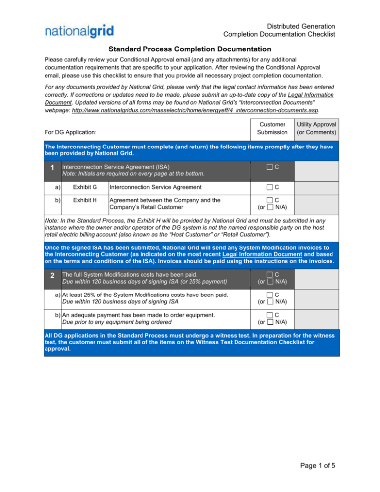
Distributed Generation Completion Documentation Checklist Standard Process Completion Documentation Please carefully review your Conditional Approval email (and any attachments) for any additional documentation requirements that are specific to your application. After reviewing the Conditional Approval email, please use this checklist to ensure that you provide all necessary project completion documentation. For any documents provided by National Grid, please verify that the legal contact information has been entered correctly. If corrections or updates need to be made, please submit an up-to-date copy of the Legal Information Document. Updated versions of all forms may be found on National Grid’s “Interconnection Documents” webpage: http://www.nationalgridus.com/masselectric/home/energyeff/4_interconnection-documents.asp. Customer Submission For DG Application: Utility Approval (or Comments) The Interconnecting Customer must complete (and return) the following items promptly after they have been provided by National Grid. Interconnection Service Agreement (ISA) Note: Initials are required on every page at the bottom. 1 a) Exhibit G Interconnection Service Agreement b) Exhibit H Agreement between the Company and the Company’s Retail Customer C C (or C N/A) Note: In the Standard Process, the Exhibit H will be provided by National Grid and must be submitted in any instance where the owner and/or operator of the DG system is not the named responsible party on the host retail electric billing account (also known as the “Host Customer” or “Retail Customer”). Once the signed ISA has been submitted, National Grid will send any System Modification invoices to the Interconnecting Customer (as indicated on the most recent Legal Information Document and based on the terms and conditions of the ISA). Invoices should be paid using the instructions on the invoices. 2 The full System Modifications costs have been paid. Due within 120 business days of signing ISA (or 25% payment) (or C N/A) a) At least 25% of the System Modifications costs have been paid. Due within 120 business days of signing ISA (or C N/A) b) An adequate payment has been made to order equipment. Due prior to any equipment being ordered (or C N/A) All DG applications in the Standard Process must undergo a witness test. In preparation for the witness test, the customer must submit all of the items on the Witness Test Documentation Checklist for approval. Page 1 of 5 Distributed Generation Completion Documentation Checklist Customer Submission Utility Approval (or Comments) The Interconnecting Customer must complete and submit the following items prior to requesting that a new meter be installed. Documentation for Metering (for net metering provide “a” & “b” OR for qualifying facilities >60kW provide “c” & “d”) 3 a) b) c) d) C Proof of Cap Allocation Net Metering System of Assurance cap allocation (visit www.massaca.org for more information) (or C N/A) Schedule Z Additional Information Required for Net Metering Service (or C N/A) (or C N/A) (or C N/A) Schedule A Form 556 Agreement to Purchase under the P-Rate Tariff FERC Qualifying Facilities Certificate 4 Exhibit A2 Simplified Certificate of Completion (must be signed by the local code official at the time of the electrical inspection.) C 5 Evidence of Insurance Refer to the ISA and the Interconnection Tariff for insurance requirements. The original must be mailed to the address in the ISA. C OR: a) Class 1 Net Metering As per 220 CMR §18.03(2) evidence of insurance is not required if net metered and ≤60kW N/A b) Government Entity As per the ISA, some Facilities owned by Government Entities are exempt from this requirement N/A 6 Utility Revenue All accounts with >60kW of generation capacity Meter Phone capable of exporting power to the National Grid Number Electric Power System (EPS) must install a dedicated phone line at the Utility Revenue Meter. Refer to the National Grid Phone Line Installation Guide for the most up-to-date specifications. Phone #: (000)000-0000 (or N/A) 7 Commissioning Must be on Electrical Company/ Installation Contractor letterhead, signed and dated by the Memo Electrical Company/ Installation Contractor AND include/provide all of the following statements with Frequency(Hz) Listing: C a) The system passed the “2 seconds shutdown, when utility disconnect is open” test. C Do Inverter relays meet NPCC Frequency requirements? See M.D.P.U. No. 1248, Section 4.2.3.2.1, Page 2 of 5 Distributed Generation Completion Documentation Checklist b) The system passed the “5 minutes before restart, after utility disconnect is closed” test. C c) A visual inspection of the system confirms that the system matches the As-Built electrical One or Three line diagram dated_______. C d) The relay frequency settings identified in the relevant interconnection standards M.D.P.U. No. 1248, Section 4.2.3.2.1b and in the Screening Memo and/or Supplemental Review Memo are adhered to and have been tested. List Inverter internal relay frequency (Hz) and time. Provide field proof, via statement/table in the memo. C Witness Test 8 If the Witness test is needed has the correct documentation been provided? (or C N/A) The Interconnecting Customer must provide clear pictures of the following pieces of equipment and plaques in both (a) wide-angle shots to provide context of the equipment locations and (b) close-up shots to ensure the legibility of any signage or permanent plaques. Note: Any permanent plaques must be suitable for the environment in which they are located and rated to last for the lifetime of the generation equipment. No stickers of any type will be accepted as permanent plaques for equipment that is located outside. All plaques as described in NEC 705.10, 705.12 (7), 690.56, 692.4 and 705.70 shall be installed when applicable. PV Plaques All generator(s) or inverter(s) C AC Utility Disconnect Switch (located outside, 24/7 accessible) C a) A permanent plaque (visible at eye level) that reads “AC Utility Disconnect Switch”. C 9 10 11 Current Limiting Device(s) (e.g. fuses and/or circuit breakers) C Page 3 of 5 Distributed Generation Completion Documentation Checklist Customer Submission 12 Utility Revenue Meter, including the following (as applicable): C a) If a phone line is required, the picture must show the phone line. (or b) A permanent plaque (visible at eye level) that includes a warning about the generator installed. c) If the AC Utility Disconnect Switch is not grouped with and adjacent to the Utility Revenue Meter, a permanent plaque (visible at eye level) that clearly identifies the location of the AC Utility Disconnect. 13 14 Customer-owned Transformer(s) (if installed) 15 Any new and existing Service Equipment (on/in/at the building) a) At each piece of Service Equipment (that is not grouped with and adjacent to all other pieces of service equipment on/in/at the building), a permanent plaque (visible at eye level) that describes and/or depicts the locations and accessibility of all pieces of service equipment on/in/at the building. 16 (or C N/A) (or C N/A) (or C N/A) (or C N/A) C (or Point of Common Coupling (PCC) as identified in the ISA (choose all applicable options “a”-“d” below) a) If the PCC is at a pole-mounted service transformer, a permanent plaque (visible at eye level, located on the pole) that includes a warning about the generator installed. b) If the PCC is at a pad-mounted service transformer, a permanent plaque (visible at eye level, located on the right door of the padmounted service transformer) that includes a warning about the generator installed. c) If the PCC is at a secondary or primary meter, the permanent plaque(s) required for the Utility Revenue Meter are sufficient. d) If the AC Utility Disconnect Switch is not grouped with and adjacent to the PCC, a permanent plaque (visible at eye level) that clearly identifies the location of the AC Utility Disconnect. C N/A) C Customer-owned Production Meter(s) (if installed) a) If the customer-owned production meter is a revenue-grade meter (or otherwise looks similar to a National Grid utility revenue meter), a permanent plaque (visible at eye level) that reads “Customer-Owned Production Meter”. Utility Approval (or Comments) C N/A) C (or C N/A) (or C N/A) (or C N/A) (or C N/A) Page 4 of 5 Distributed Generation Completion Documentation Checklist Customer Submission Utility Approval (or Comments) After National Grid has completed any EPS modifications (as identified in the ISA) and the Interconnecting Customer has successfully submitted/completed all of the items listed above (and/or identified in the Conditional Approval email) National Grid will complete the following actions. 1 Review and Approve the results of the witness test 2 Installation of new ‘net’ and/or ‘bi-directional’ meter (if applicable) a) b) 3 Requested Installed C N/A Once all items have been satisfactorily completed, National Grid’s DG group will request the installation of a new meter. N/A National Grid will generally coordinate the meter installation with the Witness Test, subject to the customer providing sufficient advanced notice. N/A Authorization to This is an official authorization to activate and Interconnect operate your generating system. C N/A (or C N/A) (or C N/A) (or C N/A) C Warning: Operating your generator prior to receiving the Authorization to Interconnect may cause damage to National Grid’s electric power system or other customers’ equipment and will likely cause billing errors, which will result in additional charges on the customer’s bill. For additional information about the distributed generation interconnection process, please refer to National Grid’s Interconnection Process webpage for Distributed Generation: http://www.nationalgridus.com/masselectric/home/energyeff/4_interconnection-process.asp. Page 5 of 5
