Introduction_rev3_112209
advertisement
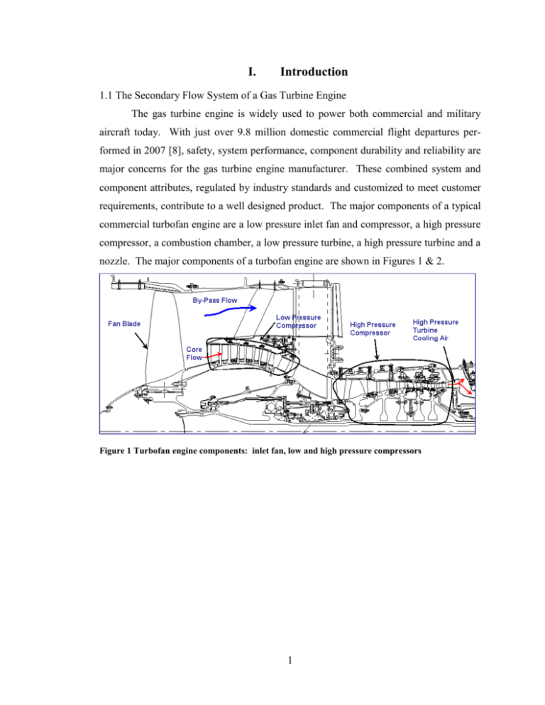
I. Introduction 1.1 The Secondary Flow System of a Gas Turbine Engine The gas turbine engine is widely used to power both commercial and military aircraft today. With just over 9.8 million domestic commercial flight departures performed in 2007 [8], safety, system performance, component durability and reliability are major concerns for the gas turbine engine manufacturer. These combined system and component attributes, regulated by industry standards and customized to meet customer requirements, contribute to a well designed product. The major components of a typical commercial turbofan engine are a low pressure inlet fan and compressor, a high pressure compressor, a combustion chamber, a low pressure turbine, a high pressure turbine and a nozzle. The major components of a turbofan engine are shown in Figures 1 & 2. Figure 1 Turbofan engine components: inlet fan, low and high pressure compressors 1 Figure 2 Turbofan engine components: combustor, high and low pressure turbines, and nozzle At the inlet of the engine the intake air flows through the fan and upon exiting is split into two main flow paths; the by-pass flow and the primary or core flow. The bypass flow is about 80% of the inlet flow and its primary function is thrust. It is channeled through the fan duct then enters the nozzle where it remixes with the core flow before exiting the rear of the engine. The remaining 20% inlet air goes through the compressors and then the combustor where it is mixed with fuel and ignited before entering the turbines. Once the core flow exits the turbines it remixes with the by-pass flow, just before entering the nozzle. One of the primary functions of the core flow is to drive the compressor. A portion of the core flow is split off near the compressor exit. This flow, called the secondary air system, bypasses the burner and is used to perform a variety of functions that are critical for safe engine operation. Figure 2 shows a simple schematic of the high pressure turbine cooling air path from the compressor exit to the high turbine inlet. Some of these functions are ventilation, sealing and purging air to disks, shafts, cavities and bearing compartments [7]. The cooling air system is designed to assure the life of the hardware, to provide thermal conditioning for clearance control, customer bleed flow, compressor starting and stability bleeds, and engine anti icing protection. The secondary air system also influences rotor thrust bearing loads, protects bearing compartments, and assures an acceptable nacelle environment. The internal air system optimizes propulsion system performance while satisfying all of the above requirements. Although each portion of the secondary air system is needed for a bal- 2 anced system, this paper will focus on the cooling air supplied to the high pressure disk and blades through a pre-swirl cooling air delivery system. The basic function of a pre-swirl system is to supply cooling air to a disk and blade, meeting the temperature, pressure, and leakage requirements of the system while minimizing the losses and work input associated with bringing air on board a rotating structure. The turbine cooling air is taken from appropriate compressor stage locations where work has been done to increase pressure. The path of the diverted high pressure secondary air is a complex configuration consisting of orifices, cavities, and component interfaces. Upon entering the pre-swirl nozzle, the high pressure cooling air typically traverses a set of static tangentially inclined nozzles, called a cascade, which turn the air in the direction of disk rotation. Turning the air imparts a tangential component to the velocity of the cooling air, thereby minimizing the heat up generated when the air comes on board the rotating structure, as defined by Euler’s equations. The pre-swirl cavity cooling air and delivery system is also known as the Tangential On Board Injection (TOBI) system. See Figure 3 for a pre-swirl rotor stator system schematic. Receiver Holes Rotating Minidisk Stationary Pre-Swirl Nozzle Figure 3 High pressure turbine The high pressure cooling air is expanded through the stationary pre-swirl nozzles where the majority of the air passes through a chamber and then is delivered to receiver holes on the rotating mini disk. The higher the pre-swirl nozzle exit tangential velocity, the 3 colder the cooling air will be as it is delivered to the blade, maximizing cooling effectiveness. The swirled cooling air exiting the pre-swirl nozzles splits and follows three paths, fulfilling separate tasks. The majority of the flow delivered to the receiver holes on the rotating mini disk is split into two directions, outward towards the gas path and inward towards the bore. As the flow travels outboard, cooling flow is delivered to the rotating blade meeting a supply pressure requirement at a particular flow level and temperature. These requirements ensure the blade will meet its life goal and satisfy rear blade attachment leakages. Blade supply pressure, temperature, and flow requirements are met at the condition where the majority of blade damage occurs, which is take-off for most engine applications. The inward path taken once exiting the receiver holes provides the flow needed to meet the requirement for high pressure turbine bore flow. This flow path has little impact on the TOBI system and will not be discussed in detail. The remaining cooling air, once exiting the pre-swirl nozzles, goes through the outer diameter labyrinth seal to supply attachment leaks and front rim cavity purge. See Figure 4 for flow paths of the high pressure turbine TOBI area. OD Seal-Dead rim cooling air and front rim cavity purge Pre-swirl cooling air Blade cooling air and attachment leaks From HPC rear hub #4 bearing compartment air HPT bore cooling air Figure 4 High pressure turbine TOBI area and flow paths 4 1.2 Problem Statement The cooling air delivered to the turbine is critical for flight safety, without it, parts would not meet life requirements and hardware failures would occur. The core flow turbine inlet air exiting the combustor is quite high and can reach temperatures over 3000oF. The high pressure turbine first stage purge flow cooling air prevents excessive hot gas ingestion, keeping the metal coatings on the vane and blade platforms from being burned off before reaching life goals. The cooling air supplied to the rotating disk and blade by the pre-swirl nozzle system is also critical to part life. The intention of this thesis is to document a method to perform a probabilistic secondary flow analysis for a high pressure turbine pre-swirl cavity capture and delivery cooling air system of the turbofan engine. The analysis will be used to quantify the variability of the cooling air delivery system due to inherent uncertainty in manufacturing processes and engine performance. In addition to quantifying the variability of the cooling air delivery system, the sensitivity of the design parameters will be determined. 1.3 Research Objectives The probabilistic flow analysis performed on the high pressure turbine secondary flow system is done using an enhanced deterministic flow model. The outputs of interest are the flow through the pre-swirl nozzle, the nozzle exit pressure and temperature, the cooling flow to the blade, rim cavity purge flow, flow to the bore, the blade supply pressure and temperature, and the pre-swirl cavity temperature. The enhancement to the deterministic flow model is applied by adding a variation to the input parameters of the flow network solver. For example the high pressure turbine inlet and exit pressures have a standard deviation of 0.5% of the average pressure with a 2 sigma variation applied to each of them. A complete list of the parameters that will be varied can be found in the analysis section and are discussed in detail there. The flow solver program consists of networks that mathematically model the entire engine, from the fan inlet to the nozzle. A flow network consists of restrictors that represent orifices, labyrinth seals, frictional losses in pipes, vortexes, etc, that are connected to chambers representing large plenums of air [2]. Each of the restrictors and chambers are defined by their associated pressure losses. See Figure 5 for an example of a flow solver network showing restrictors and chambers of the TOBI area. 5 Figure 5 Flow solver network, restrictors and chambers The probabilistic flow analysis is executed with variability in engine performance (day to day variability) and hardware geometry (engine to engine variability) yielding the variability in mass flow rates and air temperatures. After all correct and assumed deviations have been entered, and all desired outputs have been identified, the model is run. The model generates regression output, cumulative density functions, and probability density functions. The cumulative density functions are useful for determining how likely a range of values are, and probability density functions are useful for determining if enough samples were taken and distribution type of output variables. 1.4 Overview of Expected Result Usage The results of the analysis will be used to efficiently determine sources of variability in the secondary flow system while identifying the most influential geometric and performance parameters. This will allow known performance capabilities to be established promoting a more reliable and inexpensive engine. This paper will demonstrate a probabilistic study method that explores flow sensitivity of design parameters relative to the subsystem high pressure turbine single stage pre-swirl cooling air delivery and capture system of a turbofan engine. Probabilistic analysis has many applications in cost reduction, engine design, optimization, and root 6 cause analysis and has been discussed by Cloud & Stearns and others [1-3]. The results of those analyses will be discussed in the background section (section 2) of this paper. 7
