5-58 Helium is compressed by a compressor
advertisement
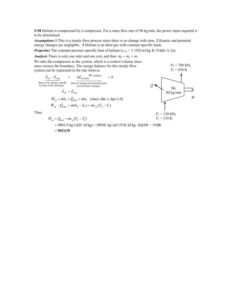
5-58 Helium is compressed by a compressor. For a mass flow rate of 90 kg/min, the power input required is to be determined. Assumptions 1 This is a steady-flow process since there is no change with time. 2 Kinetic and potential energy changes are negligible. 3 Helium is an ideal gas with constant specific heats. Properties The constant pressure specific heat of helium is cp = 5.1926 kJ/kg·K (Table A-2a). 1 m 2 m . Analysis There is only one inlet and one exit, and thus m We take the compressor as the system, which is a control volume since P2 = 700 kPa mass crosses the boundary. The energy balance for this steady-flow T2 = 430 K system can be expressed in the rate form as E E out E system0 (steady) 0 in Rate of net energy transfer · Rate of change in internal,kinetic, by heat, work, and mass Q potential,etc. energies He E in E out 90 kg/min · W W m h Q m h (since ke pe 0) in 1 out 2 W in Q out m (h2 h1 ) m c p (T2 T1 ) Thus, Win Q out m c p T2 T1 P1 = 120 kPa T1 = 310 K (90/6 0 kg/s)(20 kJ/kg) + (90/60 kg/s)(5.19 26 kJ/kg K)(430 310)K 965 kW 5-89 Air is preheated by hot exhaust gases in a cross-flow heat exchanger. The rate of heat transfer and the outlet temperature of the air are to be determined. Assumptions 1 Steady operating conditions exist. 2 The heat exchanger is well-insulated so that heat loss to the surroundings is negligible and thus heat transfer from the hot fluid is equal to the heat transfer to the cold fluid. 3 Changes in the kinetic and potential energies of fluid streams are negligible. 4 Fluid properties are constant. Properties The specific heats of air and combustion gases are given to be 1.005 and 1.10 kJ/kg.C, respectively. Analysis We take the exhaust pipes as the system, which is a control volume. The energy balance for this steady-flow system can be expressed in the rate form as E E out in E system0 (steady) Rate of net energy transfer by heat, work, and mass 0 E in E out Rate of change in internal,kinetic, potential,etc. energies m h1 Q out m h2 (since ke pe 0) Q out m c p (T1 T2 ) Then the rate of heat transfer from the exhaust gases becomes Q [m c (T T )] p in out gas (1.1 kg/s)(1.1 kJ/kg. C)(180 C 95 C) = 102.85 kW Air 95 kPa 20C 0.8 m3/s The mass flow rate of air is m (95 kPa)(0.8 m 3 /s) PV 0.904 kg/s RT (0.287 kPa.m 3 /kg.K) 293 K Exhaust gases 1.1 kg/s, 95C Noting that heat loss by the exhaust gases is equal to the heat gain by the air, the outlet temperature of the air becomes Q 102 .85 kW c p (Tc,out Tc,in ) Q m Tc,out Tc,in 20 C 133.2C cp m (0.904 kg/s)(1.00 5 kJ/kg. C) 5-62E Air is expanded in an adiabatic turbine. The mass flow rate of the air and the power produced are to be determined. Assumptions 1 This is a steady-flow process since there is no change with time. 2 The turbine is wellinsulated, and thus there is no heat transfer. 3 Air is an ideal gas with constant specific heats. Properties The constant pressure specific heat of air at the average temperature of (800+250)/2=525°F is cp = 0.2485 Btu/lbm·R (Table A-2Eb). The gas constant of air is R = 0.3704 psiaft3/lbmR (Table A-1E). 1 m 2 m . We take the turbine as the system, Analysis There is only one inlet and one exit, and thus m which is a control volume since mass crosses the boundary. The energy balance for this steady-flow system can be expressed in the rate form as E E E system0 (steady) 0 inout Rate of net energy transfer Rate of change in internal,kinetic, 500 psia by heat, work, and mass potential,etc. energies 800°F E in E out V2 m h1 1 2 2 m h2 V2 W out 2 V 2 V22 W out m h1 h2 1 2 Turbine 2 2 m c p (T1 T2 ) V1 V2 2 60 psia 250°F 50 ft3/s The specific volume of air at the exit and the mass flow rate are v2 m RT2 (0.3704 psia ft 3 /lbm R)(250 460 R) 4.383 ft 3 /lbm P2 60 psia V2 50 ft 3 /s 11.41 kg/s v 2 4.383 ft 3 /lbm V2 v 2 (11 .41 lbm/s)(4.3 83 ft 3 /lbm) m 41 .68 ft/s A2 1.2 ft 2 Similarly at the inlet, v1 RT1 (0.3704 psia ft 3 /lbm R)(800 460 R) 0.9334 ft 3 /lbm P1 500 psia V1 v 1 (11.41 lbm/s)(0.9 334 ft 3 /lbm) m 17 .75 ft/s A1 0.6 ft 2 Substituting into the energy balance equation gives V 2 V 22 W out m c p (T1 T2 ) 1 2 (17 .75 ft/s) 2 (41 .68 m/s) 2 (11 .41 lbm/s) (0.2485 Btu/lbm R)(800 250 )R 2 1559 kW 1 Btu/lbm 25,037 ft 2 /s 2 5-68 Refrigerant-134a is throttled by a capillary tube. The quality of the refrigerant at the exit is to be determined. Assumptions 1 This is a steady-flow process since there is no change with time. 2 Kinetic and potential energy changes are negligible. 3 Heat transfer to or from the fluid is negligible. 4 There are no work interactions involved. 1 m 2 m . We take the throttling valve as the Analysis There is only one inlet and one exit, and thus m system, which is a control volume since mass crosses the boundary. The energy balance for this steadyflow system can be expressed in the rate form as E in E out E system0 (steady) 0 E in E out m h1 m h2 50°C Sat. liquid h1 h2 since Q W ke Δpe 0 . R-134a The inlet enthalpy of R-134a is, from the refrigerant tables (Table A-11), T1 50 C h1 h f 123 .49 kJ/kg sat. liquid The exit quality is h2 h f 123 .49 35 .92 T2 12 C 0.422 x2 h2 h1 h fg 207 .38 -12°C
