III. LORAN-C Data Modulation
advertisement
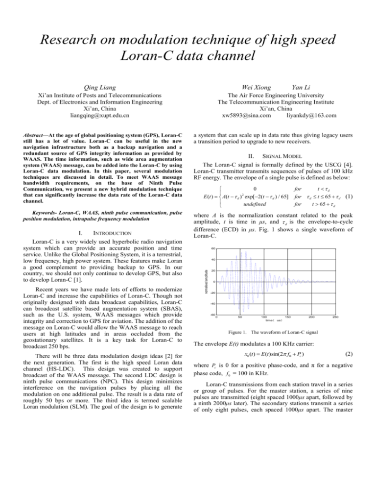
Research on modulation technique of high speed Loran-C data channel Qing Liang Wei Xiong Xi’an Institute of Posts and Telecommunications Dept. of Electronics and Information Engineering Xi’an, China liangqing@xupt.edu.cn Yan Li The Air Force Engineering University The Telecommunication Engineering Institute Xi’an, China xw5893@sina.com liyankdy@163.com Abstract—At the age of global positioning system (GPS), Loran-C still has a lot of value. Loran-C can be useful in the new navigation infrastructure both as a backup navigation and a redundant source of GPS integrity information as provided by WAAS. The time information, such as wide area augmentation system (WAAS) message, can be added into the Loran-C by using Loran-C data modulation. In this paper, several modulation techniques are discussed in detail. To meet WAAS message bandwidth requirements, on the base of Ninth Pulse Communication, we present a new hybrid modulation technique that can significantly increase the data rate of the Loran-C data channel. a system that can scale up in data rate thus giving legacy users a transition period to upgrade to new receivers. Keywords- Loran-C, WAAS, ninth pulse communication, pulse position modulation, intrapulse frequency modulation where A is the normalization constant related to the peak amplitude, t is time in μs, and d is the envelope-to-cycle difference (ECD) in μs. Fig. 1 shows a single waveform of Loran-C. INTRODUCTION Loran-C is a very widely used hyperbolic radio navigation system which can provide an accurate position and time service. Unlike the Global Positioning System, it is a terrestrial, low frequency, high power system. These features make Loran a good complement to providing backup to GPS. In our country, we should not only continue to develop GPS, but also to develop Loran-C [1]. Recent years we have made lots of efforts to modernize Loran-C and increase the capabilities of Loran-C. Though not originally designed with data broadcast capabilities, Loran-C can broadcast satellite based augmentation system (SBAS), such as the U.S. system, WAAS messages which provide integrity and correction to GPS for aviation. The addition of the message on Loran-C would allow the WAAS message to reach users at high latitudes and in areas occluded from the geostationary satellites. It is a key task for Loran-C to broadcast 250 bps. There will be three data modulation design ideas [2] for the next generation. The first is the high speed Loran data channel (HS-LDC). This design was created to support broadcast of the WAAS message. The second LDC design is ninth pulse communications (NPC). This design minimizes interference on the navigation pulses by placing all the modulation on one additional pulse. The result is a data rate of roughly 50 bps or more. The third idea is termed scalable Loran modulation (SLM). The goal of the design is to generate SIGNAL MODEL The Loran-C signal is formally defined by the USCG [4]. Loran-C transmitter transmits sequences of pulses of 100 kHz RF energy. The envelope of a single pulse is defined as below: 0 E (t ) A(t d ) 2 exp[2(t d ) / 65] undefined for t d for d t 65 d (1) for t 65 d 60 40 normalised amplitude I. II. 20 0 -20 -40 -60 0 50 100 150 time( us) 200 250 Figure 1. The waveform of Loran-C signal The envelope E(t) modulates a 100 KHz carrier: x0 (t ) E(t )sin(2 f0 Pc ) (2) where Pc is 0 for a positive phase-code, and π for a negative phase code, f 0 = 100 in KHz. Loran-C transmissions from each station travel in a series or group of pulses. For the master station, a series of nine pulses are transmitted (eight spaced 1000μs apart, followed by a ninth 2000μs later). The secondary stations transmit a series of only eight pulses, each spaced 1000μs apart. The master and each secondary in the chain transmit in a specified and precisely timed sequence. First, the master station transmits. Then, after an interval sufficient to allow the master signal to propagate throughout the coverage area, the first secondary in sequence transmits, and so forth. Each group’s pulses (nine for the master and eight for secondary stations) repeat every group repetition interval (GRI). The GRI is the length of time in microseconds between the start of one transmission of master in a Loran-C chain to the start of the next. III. LORAN-C DATA MODULATION Loran-C can’t provide enough inside time information to flag the reference pulse, and it has to be assisted another time system to complete the procedure of timing. The time information can be added into the Loran-C by using Loran-C data modulation. The main modulations are discussed here. A. Pulse Position Modulation (PPM) Pulse position modulation is a system where the arrival time of the Loran-C pulse is shifted to transmit data. The Eurofix is an example of this technique. Only the last six pulses are used and the code is balanced for every Loran-C transmission. Fig. 2 shows PPM waveform using three-level modulation (1μs advance, prompt, or 1μs delay). Intrapulse frequency modulation is a system where the difference phase and signal pattern by altering the frequency to transmit date, which changing occur after the standard tracking point. A gradual change in frequency will be result in phase changing of up to 90 degree in 100μs. Fig. 3 shows a single pulse configuration of standard Loran-C and intrapulse frequency modulation. IFM signal specification requires that 99% of the radiated power in contained within 90-110 KHz. Usually, six pulses per GRI are modulated with each pulse carrying four bits. With a GRI of 5000(0.5s), this data rate is 20×6×4=480 bits. The preference of IFM is better than PPM. C. Ninth Pulse Communication (NPC) Ninth pulse communication is a system where one pulse is added at the following of the standard group pulse of eight pulses for secondary station, nine for master station. This added pulse is solely for data broadcast. Fig. 4 shows ten pulses broadcasting for the master station. Figure 4. Ninth pulse communication for the master station NPC minimizes the number of pulses that need to be modulated. It is important for integrity of Loran-C that the eight navigation pulses are not modulated. Furthermore, since the added pulse is not used for the navigation, it can be changed in a more significant manner. Figure 2. The waveform of PPM signal B. Intrapulse Frequency Modulation (IFM) IV. A NEW MODULATION The design of Loran-C data modulation must work with the Loran-C transmitter, retain navigation, minimize interference, and maintain spectrum and some legacy receiver compatibility. On the basis of Ninth Pulse Communication, in this paper, we present a new hybrid data modulation which can achieve the data rates necessary for WAAS message transmission. The NPC only use one pulse after group of Loran-C pulses for broadcast. We can use a combination of eight phase shift and four envelope shift states to broadcast date message. This idea can be express mathematically. n present the phase shift, m present envelope shift. State 50.625 m 1.25 n( s) Figure 3. The waveform of IFM signal (3) where, n=[0,1,…7], m=[0,1,2,3]. A separation of 50.625μs may result in the desired Euclidean distance. To achieve the maximum data rates, we can combine PPM and IFM techniques, which can be called 9thIFM. The additional pulse which has shifted the arrival alters the carry frequency after the start of pulse 60μs. Here, we choice a four level system which may have phase shift of -135, -45, +45, +135 degree. Fig. 5 shows the waveform of 9thIFM. It is assumed that the station broadcasts a minimum of 20 GRI per-second, the code rate of 9thIFM can be up to 2560bps. V. CONCLUSIONS Loran-C data modulation is an important consideration in the modulation of the system. We have detail discussion about Loran-C data modulation, such as PPM, IFM, and NPC. To achieve the maximum data rates, in this paper, we present a new Loran-C data modulation-9thIFM. The 9thIFM technique is not only meet the data rate requirements for WAAS type message, but also have minimum degradation effect on the navigation capabilities in PPM, IFM. In the future, we need do the experiment to validate them. REFERENCES [1] Figure 5. The waveform of 9thIFM [2] The additional pulse which has been modulated by 9thIFM can produce 32×4=128 states (see Table 1). [3] TABLE I. State Codes Delay (μs) 0 1 2 3 0 0 0 0 ‥‥‥‥ 8.75 8.75 8.75 8.75 50.625 50.625 50.625 50.625 ‥‥‥‥ 59.375 59.375 59.375 59.375 28 29 30 31 32 33 34 35 60 61 62 63 128 STATES OF 9THIFM Phase Bias (degree) -135 -45 45 135 State Codes 64 65 66 67 -135 -45 45 135 -135 -45 45 135 92 93 94 95 96 97 98 99 -135 -45 45 135° 124 125 126 127 Delay (μs) 101.25 101.25 101.25 101.25 ‥‥‥‥ 110 110 110 110 151.875 151.875 151.875 151.875 ‥‥‥‥ 160.625 160.625 160.625 160.625 [4] Phase Bias (degree) -135 -45 45 135 [5] [6] -135 -45 45 135 -135 -45 45 135 -135 -45 45 135° [7] [8] [9] John A. “Final report: vulnerability assessment of the transportation infrastructure relying on the global positioning system”, U.S. Department of Transportation.August29, 2001. Sherman C. LO, Ben Jamin B. Peterson. “Loran data modulation: extensions and examples”, IEEE Transactions on Aerospace and Electronic Systems, vol. 43, no. 2, pp.628-644, 2007. US Coast Guard. Loran-C user handbook. US Coast Guard,Washington, DC COMDTPUB P16562.6, Nov. 1992. Xiong Wei, Hu Yong-hui, Liang Qing. “Loran-C synchronous interference suppression using improved adaptive algorithms”, Proceedings of The 4th IEEE International Conference on Wireless Communications, Networking and Mobile Computing, ChengDu, China Sep. 2010. James M. Boyer. “High speed Loran-C channel communications”. Proceedings of 29th Annual Convention and Technical Symposium of the International Loran Association, Washing,DC,2000 Sherman C.Lo , Per Enge. “Data transmission using Loran-C”. Proceedings of Department of Aeronautics and Astronautics, Stanford University, pp.1324-1330,2002. Dr.Benjamin Peterson,Perterson Integrated Geopositioning,LLC, LT Anthony Hawes , LTjg Kevin Shmihluk. “Loran data channel communications using 9th pulse modulation Version 1.1”, USCG Loran Support Unit, 2006. Su JIAN-feng LIU Xue. “Study of Loran-C 9th pulse modulation application”, In Time Transmit. Symposium on Frequency Control technology, pp.37-39, 2008. Liu Shu-jun. MATLAB 7.0 example and application of control system. China Machine Press.2006(in Chinese)G. Eason, B. Noble, and I. N. Sneddon, “On certain integrals of Lipschitz-Hankel type involving products of Bessel functions,” Phil. Trans. Roy. Soc. London, vol. A247, pp. 529– 551, April 1955.


