Universal 24 hour timer for surface-mounted
advertisement
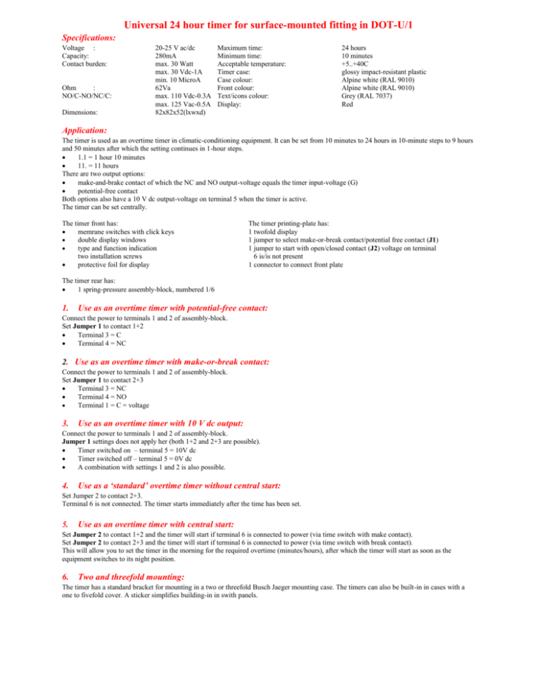
Universal 24 hour timer for surface-mounted fitting in DOT-U/1 Specifications: Voltage : Capacity: Contact burden: Ohm : NO/C-NO/NC/C: Dimensions: 20-25 V ac/dc 280mA max. 30 Watt max. 30 Vdc-1A min. 10 MicroA 62Va max. 110 Vdc-0.3A max. 125 Vac-0.5A 82x82x52(lxwxd) Maximum time: Minimum time: Acceptable temperature: Timer case: Case colour: Front colour: Text/icons colour: Display: 24 hours 10 minutes +5..+40C glossy impact-resistant plastic Alpine white (RAL 9010) Alpine white (RAL 9010) Grey (RAL 7037) Red Application: The timer is used as an overtime timer in climatic-conditioning equipment. It can be set from 10 minutes to 24 hours in 10-minute steps to 9 hours and 50 minutes after which the setting continues in 1-hour steps. 1.1 = 1 hour 10 minutes 11. = 11 hours There are two output options: make-and-brake contact of which the NC and NO output-voltage equals the timer input-voltage (G) potential-free contact Both options also have a 10 V dc output-voltage on terminal 5 when the timer is active. The timer can be set centrally. The timer front has: memrane switches with click keys double display windows type and function indication two installation screws protective foil for display The timer printing-plate has: 1 twofold display 1 jumper to select make-or-break contact/potential free contact (J1) 1 jumper to start with open/closed contact (J2) voltage on terminal 6 is/is not present 1 connector to connect front plate The timer rear has: 1 spring-pressure assembly-block, numbered 1/6 1. Use as an overtime timer with potential-free contact: Connect the power to terminals 1 and 2 of assembly-block. Set Jumper 1 to contact 1+2 Terminal 3 = C Terminal 4 = NC 2. Use as an overtime timer with make-or-break contact: Connect the power to terminals 1 and 2 of assembly-block. Set Jumper 1 to contact 2+3 Terminal 3 = NC Terminal 4 = NO Terminal 1 = C = voltage 3. Use as an overtime timer with 10 V dc output: Connect the power to terminals 1 and 2 of assembly-block. Jumper 1 settings does not apply her (both 1+2 and 2+3 are possible). Timer switched on – terminal 5 = 10V dc Timer switched off – terminal 5 = 0V dc A combination with settings 1 and 2 is also possible. 4. Use as a ‘standard’ overtime timer without central start: Set Jumper 2 to contact 2+3. Terminal 6 is not connected. The timer starts immediately after the time has been set. 5. Use as an overtime timer with central start: Set Jumper 2 to contact 1+2 and the timer will start if terminal 6 is connected to power (via time switch with make contact). Set Jumper 2 to contact 2+3 and the timer will start if terminal 6 is connected to power (via time switch with break contact). This will allow you to set the timer in the morning for the required overtime (minutes/hours), after which the timer will start as soon as the equipment switches to its night position. 6. Two and threefold mounting: The timer has a standard bracket for mounting in a two or threefold Busch Jaeger mounting case. The timers can also be built-in in cases with a one to fivefold cover. A sticker simplifies building-in in swith panels. 7. Delivery Delivery includes: 1 cable connector 2 chipboard screws 2 screw plugs 1 boring jig(sticker) for in-building in panels 1 set of instructions 8. Instructions for use Connect the timer in accordance with the instructions. The display will be off, if the timer is off with the exception of the decimal point (voltage present). The timer is set by clicking the up or down arrow-key, which will accelerate the counting up or down. By pressing the key once, the timer counts 10 minutes or one hour up or down. In order to return to the 00 position, press the up and down arrow-keys simultaneously. It is not necessary to go through 24 hours to reach 00. Depending on the selected options the timer will start as: A standard overtime timer An overtime timer with central start If a timer has been set for less than 10 hours, a flashing dot between the two displays will indicate that the timer is counting down (1.1) If a timer has been set for more than 10 hours, a flashing dot after the two displays will indicate that the timer is counting down (11.) When the last 10 minutes have expired (0.1), overtime is switched off, the two display lights will go out after a few seconds and the timer is back to its off-position (decimal point is on) It is possible to interrupt a setting by pressing the up or down arrow-keys. Warning : Never connect other voltage than 2025V ac/dc to the contact 3 and/or 4, if jumper 1 has been set to 2-3. This may seriously damage the timer. Foreign voltage may only be connected if the jumper has been set to 1-2 (potential-free contact). Dot-U/1 detail settings Jumpers are included in standard-timer delivery Pin 1 and 2 (J1) Pin 2 and 3 (J2) RoyAl Electronics B.V. Voorhorst 9 7414 BA Deventer Tel. / Fax.: 0570-640726 e.mail: info@royalelectronics.nl Internet: www.royalelectronics.nl
