CCNA Discovery
Working at a Small-to-Medium Business or ISP
Lab 5.5.4 Configuring the Cisco 2960 Switch
Instructor version
Device
S1
Host Name
CustomerSwitch
Interface
VLAN 1
IP Address
192.168.1.5
Subnet Mask
255.255.255.0
Default
Gateway
192.168.1.1
Switch Port
N/A
R1
CustomerRouter
Fa0/1
192.168.1.1
255.255.255.0
N/A
Fa0/5
H1
H1
NIC
192.168.1.2
255.255.255.0
192.168.1.1
Fa0/11
H2
H2
NIC
192.168.1.4
255.255.255.0
192.168.1.1
Fa0/18
H3
H3
NIC
192.168.1.6
255.255.255.0
192.168.1.1
None
Objectives
Configure initial switch global settings.
Configure host PCs and attach them to the switch.
Configure a router and attach it to the switch.
Configure a switch management VLAN IP address.
Verify network connectivity.
All contents are Copyright © 1992–2008 Cisco Systems, Inc. All rights reserved. This document is Cisco Public Information.
Page 1 of 14
CCNA Discovery
Working at a Small-to-Medium Business or ISP
Configure basic port security.
Configure port duplex and speed settings.
Background / Preparation
In this lab, you connect multiple hosts and a router to the switch and test connectivity. You will configure port
security, speed, and duplex settings for a switch port. This lab focuses on the basic configuration of the Cisco
2960 switch using Cisco IOS commands. The Cisco Catalyst 2960 switch comes preconfigured and only
needs to be assigned basic security information before being connected to a network. To use an IP-based
management product or Telnet with a Cisco switch, you must configure a management IP address. You will
configure VLAN 1 to provide IP access to management functions. The information in this lab applies to other
switches, however, command syntax may vary.
Required Resources
The following resources are required:
Cisco 2960 switch or other comparable switch
Router with Ethernet interface to connect to switch
Three Windows-based PCs, one with a terminal emulation program
RJ-45-to-DB-9 connector console cable
Three straight-through Ethernet cables
Access to the PC command prompt
Access to a PC network TCP/IP configuration
Note: Perform the instructions in the section “Erasing and Reloading the Switch” at the end of this lab before
continuing.
Step 1: Connect the hosts to the switch and configure them.
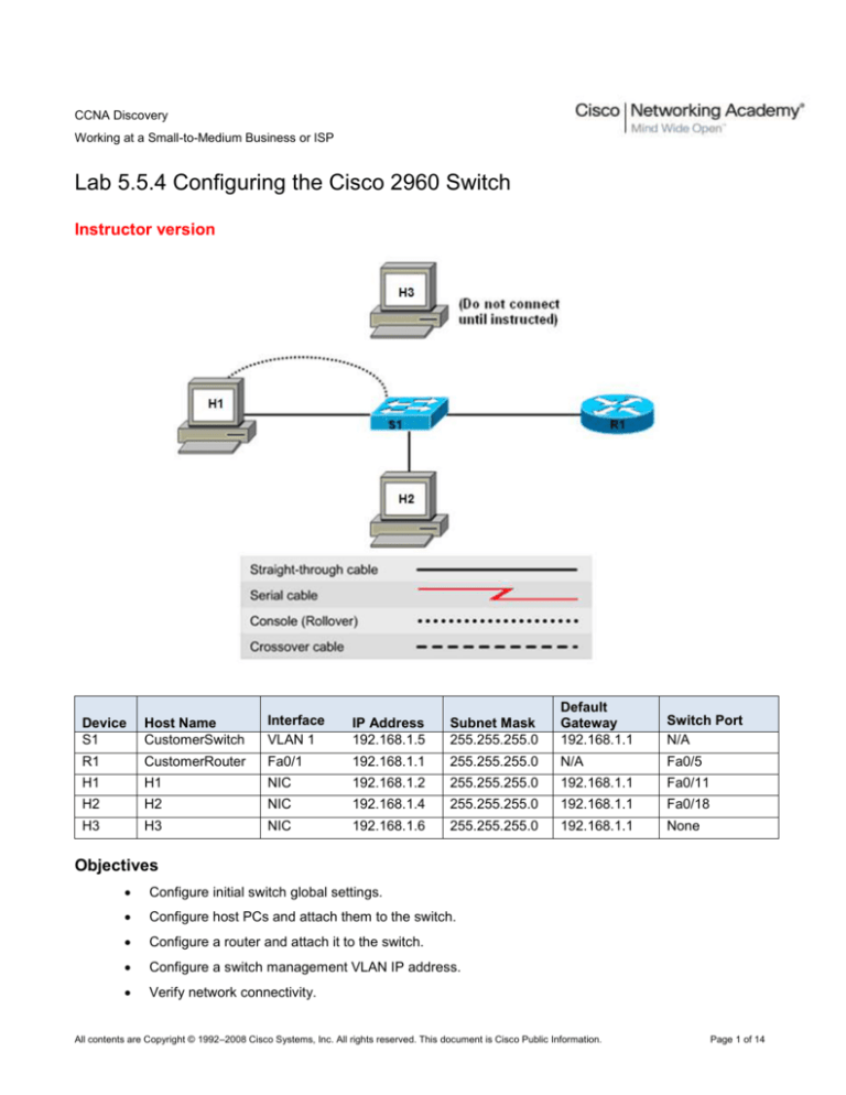
a. Connect host H1 to Fast Ethernet S1 switch port Fa0/11, and connect H2 to port Fa0/18. Configure
the hosts to use the same IP subnet for the address and mask as on the switch, as shown in the
topology diagram and table above.
b. Do not connect host H3 to the switch yet.
Step 2: Connect the router to the switch and configure the router.
Note: If necessary, see Lab 5.3.5, “Configuring Basic Router Settings with the Cisco IOS CLI,” for instructions
on setting the host name, passwords, and interface addresses.
a. Connect the router to switch port Fa0/5.
b. Configure the router with the host name CustomerRouter.
c.
Configure the console access and password, vty access and password, and enable secret password.
d. Configure the router Fa0/1 interface as shown in the topology table.
Step 3: Configure the switch.
a. Configure the switch with the host name CustomerSwitch.
Switch>enable
Switch#config terminal
Switch(config)#hostname CustomerSwitch
b. Set the privilege exec mode password to cisco.
All contents are Copyright © 1992–2008 Cisco Systems, Inc. All rights reserved. This document is Cisco Public Information.
Page 2 of 14
CCNA Discovery
Working at a Small-to-Medium Business or ISP
CustomerSwitch(config)#enable password cisco
c.
Set the privilege exec mode secret password to cisco123.
CustomerSwitch(config)#enable secret cisco123
d. Set the console password to cisco123.
CustomerSwitch(config)#line console 0
CustomerSwitch(config-line)#password cisco123
e. Configure the console line to require a password at login.
CustomerSwitch(config-line)#login
f.
Set the vty password to cisco123.
CustomerSwitch(config-line)#line vty 0 15
CustomerSwitch(config-line)#password cisco123
g. Configure the vty to require a password at login.
CustomerSwitch(config-line)#login
CustomerSwitch(config-line)#end
Step 4: Configure the management interface on VLAN 1.
a. Enter global configuration mode. Remember to use the new password.
CustomerSwitch>enable
CustomerSwitch#configure terminal
b. Enter the interface configuration mode for VLAN 1:
CustomerSwitch(config)#interface vlan 1
c.
Set the IP address, subnet mask, and default gateway for the management interface. The IP address
must be valid for the local network where the switch is installed.
CustomerSwitch(config-if)#ip address 192.168.1.5 255.255.255.0
CustomerSwitch(config-if)#no shutdown
CustomerSwitch(config-if)#exit
CustomerSwitch(config)#ip default-gateway 192.168.1.1
CustomerSwitch(config)#end
Step 5: Verify the configuration of the switch.
a. Verify that the IP address of the management interface on the switch VLAN 1 and the IP address of
host H1 are on the same local network. Use the show running-configuration command to check the
IP address configuration of the switch.
CustomerSwitch#show running-configuration
Building configuration...
Current configuration : 1283 bytes
!
version 12.2
no service pad
hostname CustomerSwitch
!
enable secret 5 $1$XUe/$ch4WQ/SpcFCDd2iqd9bda/
enable password cisco
!
interface FastEthernet0/1
!
All contents are Copyright © 1992–2008 Cisco Systems, Inc. All rights reserved. This document is Cisco Public Information.
Page 3 of 14
CCNA Discovery
Working at a Small-to-Medium Business or ISP
*** Output Omitted ***
!
interface FastEthernet0/24
!
interface Vlan1
ip address 192.168.1.5 255.255.255.0
no ip route-cache
!
ip default-gateway 192.168.1.1
ip http server
!
line con 0
password cisco123
login
line vty 0 4
password cisco123
login
line vty 5 15
password cisco123
login
!
end
b. Save the configuration.
CustomerSwitch#copy running-config startup-config
Step 6: Verify connectivity using ping and Telnet.
a. To verify that the switch and router are correctly configured, ping the router Fa0/1 interface (default
gateway) IP address from the switch CLI.
b. Are the pings successful? ________ Yes
c.
To verify that the hosts and switch are correctly configured, ping the switch IP address from host H1.
d. Are the pings successful? _________ Yes
e. If the ping is not successful, verify the connections and configurations again. Check to ensure that all
cables are correct and that connections are seated. Check the host, switch, and router configurations.
f.
Open a command prompt on host H1, and telnet the IP address assigned to switch management
VLAN 1.
g. Enter the vty password configured in Step 3. What is the result? __________________________
Gained remote IP access to the switch CLI.
h. At the switch prompt, issue the show version command.
CustomerSwitch>show version
Cisco IOS Software, C2960 Software (C2960-LANBASE-M), Version
12.2(0.0.16)FX, CISCO
DEVELOPMENT TEST VERSION
Copyright (c) 1986-2005 by Cisco Systems, Inc.
Compiled Tue 17-May-05 01:43 by yenanh
ROM: Bootstrap program is C2960 boot loader
BOOTLDR: C2960 Boot Loader (C2960-HBOOT-M), Version 12.2 [lqianflo_pilsner 100]
Switch uptime is 3 days, 20 hours, 8 minutes
System returned to ROM by power-on
All contents are Copyright © 1992–2008 Cisco Systems, Inc. All rights reserved. This document is Cisco Public Information.
Page 4 of 14
CCNA Discovery
Working at a Small-to-Medium Business or ISP
System image file is "flash:c2960-lanbase-mz.122-0.0.16.FX.bin"
cisco WS-C2960-24TC-L (PowerPC405) processor with 61440K/4088K bytes of
memory.
Processor board ID FHH0916001J
Last reset from power-on
Target IOS Version 12.2(25)FX
1 Virtual Ethernet interface
24 FastEthernet interfaces
2 Gigabit Ethernet interfaces
The password-recovery mechanism is enabled.
64K bytes of flash-simulated non-volatile configuration memory.
Base ethernet MAC Address
: 00:0B:FC:FF:E8:80
Motherboard assembly number
: 73-9832-02
Motherboard serial number
: FHH0916001J
Motherboard revision number
: 01
System serial number
: FHH0916001J
Hardware Board Revision Number : 0x01
Switch
Ports
---------*
1
26
LANBASE-M
Model
----WS-C2960-24TC-L
SW Version
---------12.2(0.0.16)FX
SW Image
---------C2960-
Configuration register is 0xF
i.
What is the Cisco IOS version of this switch? ___________________ Answers vary (e.g.
12.2(25)FX in this example)
j.
Type quit at the switch command prompt to terminate the Telnet session.
Step 7: Determine which MAC addresses the switch has learned.
a. From the Windows command prompt, get the Layer 2 addresses of the PC network interface card for
each host by using the ipconfig /all command.
Host H1: _______________________________________________ Answers vary
Host H2: _______________________________________________ Answers vary
Host H3: _______________________________________________ Answers vary
b. Determine which MAC addresses the switch has learned by using the show mac-address-table
command at the privileged exec mode prompt.
CustomerSwitch#show mac-address-table
Mac Address Table
------------------------------------------Vlan
Mac Address
Type
Ports
------------------------All
000b.be7f.ed40
STATIC
CPU
All
0100.0ccc.cccc
STATIC
CPU
All
0100.0ccc.cccd
STATIC
CPU
All
0100.0cdd.dddd
STATIC
CPU
1
000b.db04.a5cd
DYNAMIC
Fa0/5
1
000c.3076.8380
DYNAMIC
Fa0/11
1
000d.1496.36ad
DYNAMIC
Fa0/18
Total Mac Addresses for this criterion: 7
All contents are Copyright © 1992–2008 Cisco Systems, Inc. All rights reserved. This document is Cisco Public Information.
Page 5 of 14
CCNA Discovery
Working at a Small-to-Medium Business or ISP
c.
How many dynamic addresses are there? ____________________________ Three (H1, H2, and
router R1)
d. Do the MAC addresses match the host MAC addresses? _______________ Yes
e. Review the options that the mac-address-table command has by using the ? help feature.
CustomerSwitch(config)#mac-address-table ?
address
address keyword
aging-time
aging-time keyword
count
count keyword
dynamic
dynamic entry type
interface
interface keyword
multicast
multicast info for selected wildcard
notification MAC notification parameters and history table
static
static entry type
vlan
VLAN keyword
|
Output modifiers
<cr>
f.
Set up a static MAC address on the Fast Ethernet interface 0/18. Use the address that was recorded
for H2 in Step 7. The MAC address XXXX.YYYY.ZZZZ is used in the example statement only.
CustomerSwitch(config)#mac-address-table static XXXX.YYYY.ZZZZ interface
fastethernet 0/18 vlan 1
g. Verify the MAC address table entries.
CustomerSwitch#show mac-address-table
Mac Address Table
------------------------------------------Vlan
---All
All
All
All
1
1
1
Mac Address
----------000b.be7f.ed40
0100.0ccc.cccc
0100.0ccc.cccd
0100.0cdd.dddd
000b.db04.a5cd
000c.3076.8380
000d.1496.36ad
Type
-------STATIC
STATIC
STATIC
STATIC
DYNAMIC
DYNAMIC
STATIC
Ports
----CPU
CPU
CPU
CPU
Fa0/5
Fa0/11
Fa0/18
h. How many total MAC addresses are there now? ________________________ Three
i.
What type are they? ____________________________________________ Two dynamic (Fa0/5 and
Fa0/11) and one static (Fa0/18) Other static addresses are assigned to the switch CPU internally.
Step 8: Configure basic port security.
a. Determine the options for setting port security on Fast Ethernet interface 0/18.
CustomerSwitch#configure terminal
CustomerSwitch(config)#interface fastEthernet 0/18
CustomerSwitch(config-if)#switchport port-security ?
aging Port-security aging commands
mac-address Secure mac address
maximum Max secure addrs
violation Security Violation Mode
b. Remove the static mac address from FastEthernet interface 0/18. Use the address that was recorded
for H2 in Step 7. The MAC address XXXX.YYYY.ZZZZ is used in the example statement only.
All contents are Copyright © 1992–2008 Cisco Systems, Inc. All rights reserved. This document is Cisco Public Information.
Page 6 of 14
CCNA Discovery
Working at a Small-to-Medium Business or ISP
CustomerSwitch(config-if)#no mac-address-table static XXXX.YYYY.ZZZZ
interface fastethernet 0/18 vlan 1
c.
To allow the switch port FastEthernet 0/18 to accept only one device, configure port security.
CustomerSwitch(config-if)#switchport mode access
CustomerSwitch(config-if)#switchport port-security
CustomerSwitch(config-if)#switchport port-security mac-address sticky
CustomerSwitch(config-if)#end
c.
Check the port security settings.
CustomerSwitch#show port-security
Secure Port
MaxSecureAddr CurrentAddr SecurityViolation Security Action
(Count)
(Count)
(Count)
--------------------------------------------------------------------------Fa0/18
1
0
0
Shutdown
---------------------------------------------------------------------------
d. What is the security action for port Fa0/18 if a security violation occurs? _______________ Shutdown
e. What is the maximum secure address count? ____________ One
f.
Display the running configuration.
Note: Some output is omitted in the following display.
CustomerSwitch#show running-config
Building configuration...
Current configuration : 1452 bytes
version 12.2
hostname CustomerSwitch
!
interface FastEthernet0/1
!
interface FastEthernet0/2
!
interface FastEthernet0/3
!
interface FastEthernet0/18
switchport mode access
switchport port-security
switchport port-security mac-address sticky
!
interface FastEthernet0/5
!
*** Output Omitted ***
mac-address-table static 000b.db04.a5cd vlan 1 interface
FastEthernet0/18
!
end
g. Are there statements that directly reflect the security implementation in the listing of the running
configuration? ____________________________________________________________
Yes, security commands previously entered
Step 9: Connect a different PC to the secure switch port.
a. If you do not have another PC available (H3) or you cannot disconnect the PC, go to alternative Step
9.
All contents are Copyright © 1992–2008 Cisco Systems, Inc. All rights reserved. This document is Cisco Public Information.
Page 7 of 14
CCNA Discovery
Working at a Small-to-Medium Business or ISP
b. Disconnect host H2 from Fast Ethernet 0/18, and connect host H3 to the port. H3 has not yet been
attached to the switch. From H3, ping the switch address 192.168.1.5 to generate some traffic.
c.
Record any observations at the PC and the switch terminal session.
______________________________________________________________________________
______________________________________________________________________________
The PC should not be able to ping, and the switch console should generate error messages indicating
that the port is being shut down.
01:11:12: %PM-4-ERR_DISABLE: psecure-violation error detected on Fa0/18, putting
Fa0/18 in err-disable state
01:11:12: %PORT_SECURITY-2-PSECURE_VIOLATION: Security violation occurred, cause
d by MAC address 000c.3076.8380 on port FastEthernet0/18.
01:11:13: %LINEPROTO-5-UPDOWN: Line protocol on Interface FastEthernet0/18, chang
ed state to down
01:11:14: %LINK-3-UPDOWN: Interface FastEthernet0/18, changed state to down
d. View the configuration information for just Fast Ethernet port 0/18.
CustomerSwitch#show interface fastethernet 0/18
e. What is the state of this interface?
Fast Ethernet 0/18 is ________________ Down, and the line protocol is _____________. Down
Alternative Step 9: (Optional)
Step 10: Reactivate the port.
a. Clear the sticky address entry for port Fa0/18 using the clear port-security command.
S1#clear port-security sticky interface fa0/18 access
b. To return the interface from error disable to administratively up, enter the shutdown command
followed by the no shutdown command.
S1(config)#interface fa0/18
S1(config-if)#shutdown
S1(config-if)#no shutdown
c.
Enter the original host or change the MAC address to its original value. Ping from the command
prompt. You can ping multiple times or use the ping 192.168.1.5 –n 100 command, which sets the
number of ping packets to 100, instead of 4.
Step 11: Set speed and duplex options for the ports.
a. Switch port settings default to auto-duplex and auto-speed. If a computer with a 100 Mbps NIC is
attached to the port, it automatically goes into full-duplex 100 Mbps mode. If a hub is attached to the
switch port, it normally goes into half-duplex 10 Mbps mode.
b. Issue the show interfaces command to see the setting for ports Fa0/5, Fa0/11, and Fa0/18. This
command generates a large amount of output. Press the spacebar until you can see all the
information for these ports. What are the duplex and speed settings for these ports?
Port Fa0/5 ________________________________ Full duplex, 100 Mbps
Port Fa0/11 ________________________________ Full duplex, 100 Mbps
Port Fa0/18 ________________________________ Auto-duplex, auto-speed
c.
It is sometimes necessary to set the speed and duplex of a port to ensure that it operates in a
particular mode. You can set the speed and duplex with the duplex and speed commands while in
All contents are Copyright © 1992–2008 Cisco Systems, Inc. All rights reserved. This document is Cisco Public Information.
Page 8 of 14
CCNA Discovery
Working at a Small-to-Medium Business or ISP
interface configuration mode. To force Fast Ethernet port 5 to operate at half duplex and 10 Mbps,
issue the following commands:
CustomerSwitch>enable
CustomerSwitch#Config Terminal
CustomerSwitch(config-if)#interface fastEthernet 0/10
CustomerSwitch(config-if)#speed 10
CustomerSwitch(config-if)#duplex half
CustomerSwitch(config-if)#end
CustomerSwitch#
d. Issue the show interfaces command again. What is the duplex and speed setting for Fa0/5 now?
________________________________ Half duplex, 10 Mbps
Step 12: Exit the switch.
a. Type exit to leave the switch and return to the welcome screen.
Switch#exit
b. When the steps are completed, turn off all the devices. Remove and store the cables and adapter.
Step 13: Reflection.
a. Which password needs to be entered to switch from user mode to privilege exec mode on the Cisco
switch, and why?
____________________________________________________________________________
____________________________________________________________________________
The secret password of cisco123 needs to be entered. When a secret password is defined, the
regular password is disabled.
b. Which symbol is used to show a successful ping in the Cisco IOS software?
____________________________________________________________________________
The ! (exclamation mark) represents a successful ping response.
c.
What is the benefit of using port security? ___________________________________________
_____________________________________________________________________________
Answers will vary. Controls how many and which PCs can be attached to a switch port.
d. What other port-related security steps could be taken to further improve switch security?
_____________________________________________________________________________
_____________________________________________________________________________
Answers will vary. Could disable unused ports.
All contents are Copyright © 1992–2008 Cisco Systems, Inc. All rights reserved. This document is Cisco Public Information.
Page 9 of 14
CCNA Discovery
Working at a Small-to-Medium Business or ISP
Erasing and Reloading the Switch
For the majority of the labs in CCNA Discovery, it is necessary to start with an unconfigured switch. Using a
switch with an existing configuration may produce unpredictable results. The following instructions prepare
the switch prior to performing the lab so that previous configuration options do not interfere. Instructions are
provided for the 2900 and 2950 series switches.
a. Enter privileged EXEC mode by typing enable. If prompted for a password, enter class (if that does
not work, ask the instructor).
Switch>enable
b. Remove the VLAN database information file.
Switch#delete flash:vlan.dat
Delete filename [vlan.dat]?[Enter]
Delete flash:vlan.dat? [confirm] [Enter]
If there was no VLAN file, this message is displayed:
%Error deleting flash:vlan.dat (No such file or directory)
c.
Remove the switch startup configuration file from NVRAM.
Switch#erase startup-config
The responding line prompt is:
Erasing the nvram filesystem will remove all files! Continue? [confirm]
Press Enter to confirm.
The response should be:
Erase of nvram: complete
d. Check that the VLAN information was deleted in Step b by using the show vlan command. If the
VLAN information was deleted, go to Step e and restart the switch using the reload command.
If previous VLAN configuration information (other than the default management VLAN 1) is still
present, you must power cycle the switch (hardware restart) instead of issuing the reload command.
To power cycle the switch, remove the power cord from the back of the switch or unplug it, and then
plug it back in.
e. Restart the software using the reload command in privileged EXEC mode.
Note: This step is not necessary if the switch was restarted using the power cycle method.
1) At the privileged EXEC mode, enter the reload command:
Switch(config)#reload
The responding line prompt is:
System configuration has been modified. Save? [yes/no]:
Type n, and then press Enter.
The responding line prompt is:
Proceed with reload? [confirm] [Enter]
The first line of the response is:
Reload requested by console.
After the switch has reloaded, the line prompt is:
Would you like to enter the initial configuration dialog? [yes/no]:
All contents are Copyright © 1992–2008 Cisco Systems, Inc. All rights reserved. This document is Cisco Public Information.
Page 10 of 14
CCNA Discovery
Working at a Small-to-Medium Business or ISP
Type n, and then press Enter.
The responding line prompt is:
Press RETURN to get started! [Enter]
Erasing and reloading the router
a. Enter privileged EXEC mode by typing enable.
Router>enable
b. In privileged EXEC mode, enter the erase startup-config command.
Router#erase startup-config
The responding line prompt is:
Erasing the nvram filesystem will remove all files! Continue?
[confirm]
c.
Press Enter to confirm.
The response is:
Erase of nvram: complete
d. In privileged EXEC mode, enter the reload command.
Router(config)#reload
The responding line prompt is:
System configuration has been modified. Save? [yes/no]:
e. Type n, and then press Enter.
The responding line prompt is:
Proceed with reload? [confirm]
f.
Press Enter to confirm.
In the first line of the response is:
Reload requested by console.
After the router has reloaded the line prompt is:
Would you like to enter the initial configuration dialog? [yes/no]:
g. Type n, and then press Enter.
The responding line prompt is:
Press RETURN to get started!
h. Press Enter.
The router is ready for the assigned lab to be performed.
All contents are Copyright © 1992–2008 Cisco Systems, Inc. All rights reserved. This document is Cisco Public Information.
Page 11 of 14
CCNA Discovery
Working at a Small-to-Medium Business or ISP
CustomerRouter Running Configuration
CustomerRouter#show running-config
Building configuration...
Current configuration : 681 bytes
!
version 12.2
service timestamps debug uptime
service timestamps log uptime
no service password-encryption
!
hostname CustomerRouter
!
enable secret 5 $1$z8BM$WW4yylvopXdi64Oigj4sQ1
enable password cisco
!
memory-size iomem 10
ip subnet-zero
!
call rsvp-sync
!
interface FastEthernet0/1
ip address 192.168.1.1 255.255.255.0
duplex auto
speed auto
!
interface Serial0/0
no ip address
shutdown
no fair-queue
!
interface Serial0/1
no ip address
shutdown
!
ip classless
ip http server
!
dial-peer cor custom
!
line con 0
password cisco123
login
line aux 0
line vty 0 4
password cisco123
login
line vty 5 15
password cisco123
login
!
end
All contents are Copyright © 1992–2008 Cisco Systems, Inc. All rights reserved. This document is Cisco Public Information.
Page 12 of 14
CCNA Discovery
Working at a Small-to-Medium Business or ISP
CustomerSwitch Running config
CustomerSwitch#show running-config
Building configuration...
Current configuration : 1535 bytes
!
version 12.1
no service pad
service timestamps debug uptime
service timestamps log uptime
no service password-encryption
!
hostname CustomerSwitch
!
enable secret 5 $1$XUe/$ch4WQ/SpcFCDd2iqd9bda/
enable password cisco
!
ip subnet-zero
!
!
spanning-tree mode pvst
no spanning-tree optimize bpdu transmission
spanning-tree extend system-id
!
interface FastEthernet0/1
!
interface FastEthernet0/2
!
interface FastEthernet0/3
!
interface FastEthernet0/4
!
interface FastEthernet0/5
!
interface FastEthernet0/6
!
interface FastEthernet0/7
!
interface FastEthernet0/8
!
interface FastEthernet0/9
!
interface FastEthernet0/10
speed 10
duplex half
!
interface FastEthernet0/11
!
interface FastEthernet0/12
!
interface FastEthernet0/13
!
interface FastEthernet0/14
!
interface FastEthernet0/15
All contents are Copyright © 1992–2008 Cisco Systems, Inc. All rights reserved. This document is Cisco Public Information.
Page 13 of 14
CCNA Discovery
Working at a Small-to-Medium Business or ISP
!
interface FastEthernet0/16
!
interface FastEthernet0/17
!
interface FastEthernet0/18
switchport mode access
switchport port-security
switchport port-security mac-address sticky
switchport port-security mac-address sticky 0007.e963.ce53
!
interface FastEthernet0/19
!
interface FastEthernet0/20
!
interface FastEthernet0/21
!
interface FastEthernet0/22
!
interface FastEthernet0/23
!
interface FastEthernet0/24
!
interface Vlan1
ip address 192.168.1.5 255.255.255.0
no ip route-cache
!
ip default-gateway 192.168.1.1
ip http server
!
line con 0
password cisco123
login
line vty 0 4
password cisco123
login
line vty 5 15
password cisco123
login
!
mac-address-table static 000b.db04.a5cd vlan 1 interface FastEthernet0/1
!
end
CustomerSwitch#
All contents are Copyright © 1992–2008 Cisco Systems, Inc. All rights reserved. This document is Cisco Public Information.
Page 14 of 14


