AP* Physics B
OPTICS
FACTS OF LIGHT
•
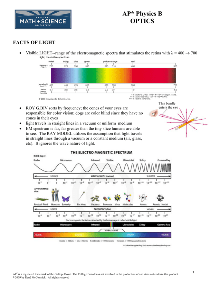
Visible LIGHT--range of the electromagnetic spectra that stimulates the retina with λ = 400 → 700
•
ROY G.BIV sorts by frequency; the cones of your eyes are
responsible for color vision; dogs are color blind since they have no
cones in their eyes
light travels in straight lines in a vacuum or uniform medium
EM spectrum is far, far greater than the tiny slice humans are able
to see. The RAY MODEL utilizes the assumption that light travels
in straight lines through a vacuum or a constant medium (air, glass,
etc). It ignores the wave nature of light.
•
•
AP7 is a registered trademark of the College Board. The College Board was not involved in the production of and does not endorse this product.
8 2009 by René McCormick. All rights reserved
1
SPEED OF LIGHT
•
•
•
•
•
Before people were enlightened (Get it?) in the 1700's --light was thought to be instantaneous
Galileo—1st to say light had finite speed & developed a method of determining speed but alas, too fast
for him!!
Ole Roemer--Danish astronomer (1644-1710)--1st to determine light traveled with measurable speed.
1668-1674 70 measurements of one moon of Jupiter named Io (pronounced as “I owe” as in “I owe
my physics teacher many thanks for illuminating the more difficult concepts in physics”.) were made
with a standard deviation of 14 seconds. In 1676 Roemer calculated 22 minutes to cross Earth's diameter
less than 1 second to cross entire Earth
1926--Albert Michelson measured time light required to make a round trip through a pipe between 2
mountains in California, 35 km apart
2.997996 " 0.00004 × 10⁸ m/s
☺ Michelson was the FIRST AMERICAN TO WIN THE NOBEL PRIZE (in 1907)
1960's--lasers better method of measuring the speed of light v = c = f λ
using time recorded by atomic clocks!!
The measurement was refined in 1983 299 792 458 m/s
You can continue to use 3.00 × 10⁸ m/s
SOURCES OF LIGHT
luminous--body emits light
illuminated--body reflects light
incandescent--glows HOT; luminous; W (that would be tungsten’s chemical symbol) wire is heated by electricity
and glows inside a light bulb
luminous flux, P--rate at which light is emitted from a source
lumen--lm--unit of flux 100W bulb = 1750 lm
1750 lx
illuminance, E--lm/m2 or lux, lx; For a sphere with a 1.0 m radius; E =
4π m 2
If you double the sphere's radius
E = 1750 lm = 1750 lx
16π
4π (2m)2
candela,cd--measures luminous intensity
1750 lx = 139 cd
4π
increased illumination is caused by either:
increase flux of alternate source
or decrease distance between source and surface
illuminance = E = P
4π d2
perpendicular line between source and surface
point sources
LIGHT AND MATTER
Words often used to describe light’s attempt to travel through an object:
transparent--through; transmitted
translucent—sort of through; sort of transmitted; foggy
opaque--not through; absorbed/reflected all light; no transmission
AP7 is a registered trademark of the College Board. The College Board was not involved in the production of and does not endorse this product.
8 2009 by René McCormick. All rights reserved
2
COLOR (red is my favorite!)
•
•
1666—Newton (very busy guy)--"spectrum" from prism--each color
different λ
Primary colors of light (not the crayons or paint pigments you
learned as primary colors of pigments)
o red + green + blue light = white light, therefore these are the
three primary colors of light
o Once upon a time, there was only black and white TV
(gasp!), and when “personal” computers came out, the
monitors were also only black and white.
o When “color” monitors came available for purchase,
computer geeks rejoiced! The monitors were universally
called “RGB” monitors since the primary colors of light were
systematically “blended” to create 32 (cheap) or 256
(expensive) colors of light. We were so easy to please back
then!
•
Secondary colors of light:
r + g = yellow
b + g = cyan
r + b = magenta
y + b = white; yellow is complementary to blue: y:b c:r m:g
black--absorption or reflected light
•
PIGMENTS--colored material
o dye—molecules usually containing an element with unpaired d electrons (it’s a long sordid
chemistry explanation) such as: titanium(IV) dioxide @ white; chromium(III) oxide @ green;
cadmium sulfate (Cd only makes +2 ions and you’re supposed to just know that, so it is
deprived of a Roman numeral indicating its charge…in case you were curious.) @ yellow
o pigments mix to form suspensions NOT solutions @ subtractive process
o primary pigments absorb 1 color from white light--yellow, cyan, magenta
o secondary pigments absorb 2 colors and reflect one--red, green, blue
o primary pig. = secondary light
secondary pig. = primary light
o y + b = black--all light is absorbed, none reflected
o y:b, c:r, m:g @ complementary pigments
POLARIZATION of Light
•
•
•
•
only transverse waves can be polarized
ordinary light contains EM waves vibrating in every
direction perpendicular to travel. Each wave can be
resolved into 2 perpendicular components
polarizer--½ light waves pass through @ intensity
decreases by ½ (Go, figure!)
repeat process @ perpendicular no light through @
parallel most light transmitted
AP7 is a registered trademark of the College Board. The College Board was not involved in the production of and does not endorse this product.
8 2009 by René McCormick. All rights reserved
3
HOW LIGHT BEHAVES AT A BOUNDARY
•
LAW OF REFLECTION: angle of incidence = angle of reflection,
∠i = ∠r
or θi = θr
•
both ∠'s measure from normal and n, ray i, ray r all lie in the same
plane
•
•
•
•
•
diffuse reflection--reflection off rough surface
regular reflection--reflection off smooth surface
REFRACTION OF LIGHT--light travels at different speeds in different
media
optically dense--media that slows light's speed; light bends/changes
direction if ∠i … 0 at the boundary between media as rays enter more
dense media (travel slower) refraction TOWARD the normal
∠ref smaller than ∠ incidence; as rays enter less dense media (travel
faster) refraction AWAY from the normal
∠ref smaller than ∠ incidence
Snell's Law
Willebrord Snell (1591-1626) Dutch:
ni sinθi = nr sinθr
a ray of light bends so ratio of
sin∠ i : sin ∠r is a constant
AP7 is a registered trademark of the College Board. The College Board was not involved in the production of and does not endorse this product.
8 2009 by René McCormick. All rights reserved
4
•
Index of Refraction--when light travels from a vacuum to a new medium the constant is
sin θi
n=
sin θ r
INDEX OF REFRACTION AND THE SPEED OF LIGHT
Refraction occurs because the speed of light depends on medium through
which it travels
sin θi
c
Can you feel some problems coming on?
AND n =
ns =
vs
sin θ r
Example 7 (yeah, it=s a bit out of order starting with #7--humor me!)
Calculate the speed of light in diamond. (Table of indices of refraction given on previous page.)
Example 8
Light strikes a flat piece of glass at an incident angle of 60E.
If the index of refraction of the glass is 1.50
a) What is the angle of refraction θA in the glass.
b) What is the angle θB at which the ray emerges from the glass?
AP7 is a registered trademark of the College Board. The College Board was not involved in the production of and does not endorse this product.
8 2009 by René McCormick. All rights reserved
5
Example 9
A swimmer has dropped her goggles in the shallow end of a pool, marked at 1.0 m
deep. But the goggles don=t look that deep. Why? How deep do the goggles
appear to be when you look straight down into the water?
APPLICATIONS OF REFLECTED AND REFRACTED LIGHT
Total Internal Reflection--light does not emerge! Best practical application? Fiber optic technology.
As light moves into a medium that is more dense @ refraction is away from normal @ ∠ref larger than ∠i
when this ∠ is HUGE, there is NO REFRACTED
RAY ∴ total internal reflection.
The ∠ref = 90E and light cannot escape!!
ni sin θi = nref sin θref
nwater sin θi = nair sin θref
(1.33)sin θi = (1.00)sin θref
sin θi = (1) sin 90E
1.33
∴ θi = 48.8E = θc
θc is the critical ∠. Use Snell's law and set θi = θc
; nref = 1.000 & θref = 90.0E
ANY ray reaching the boundary at θc or above causes total internal
reflection
FIBER OPTICS--used to transmit information with light instead of
electricity
Television, TV, radio vary the amplitude of the signal
as binary bits--0's and 1's to communicate information
13 = 1,1,0,1 and 3 = 0,0,1,1
1 on 0 off @ creates pulses of light for communication
AP7 is a registered trademark of the College Board. The College Board was not involved in the production of and does not endorse this product.
8 2009 by René McCormick. All rights reserved
6
EFFECTS OF REFRACTION
Mirages--change in nair due to temperature gradient. Ray aimed at road encounters smaller n, bent away from
normal @ you see light reflected from the sky which looks like light reflected from a puddle
Shift in position of object in a liquid--appears closer to surface than it is
sunset/sunrise--sunlight is refracted by Earth's atmosphere
• DISPERSION OF LIGHT
ns depends on λ of incident light
In glass--red fastest, smallest n, therefore bent least. Violet slower, largest n, therefore bent most.
o dispersion--separation into a spectrum by refraction
o different light sources different spectra
o rain droplets and sunshine rainbow!! Back of droplet light undergoes total internal reflection while out
of droplet (front) light is refracted and dispersed red light = 42E & blue light = 40E w/respect to sun's rays
•
OBJECTS AND THEIR IMAGES IN MIRRORS
PLANE MIRROR--flat, smooth, regular reflection, f/b or lft/rt
reversed image
o object--source of diverging light rays; luminous or illuminated
o image--point where extended rays apparently intersect
o virtual image--no source is really there; rays appear to diverge w/o
doing so
o real image--rays from object converge
o upright↑ inverted↓
CONCAVE MIRRORS--reflects light from inner surface
part of hollow sphere
radius 0 r
geometric center of sphere 0 C
principal axis--CA, straight ⊥ line to surface of mirror
focal point 0 F--where light rays converge on principal axis
midpoint of CA for small angles of incidence
focal length 0 f— ½ radius of curvature
occurs at
AP7 is a registered trademark of the College Board. The College Board was not involved in the production of and does not endorse this product.
8 2009 by René McCormick. All rights reserved
7
•
SPHERICAL ABERRATION
o & rays converge @ F only if close to principal
axis
o Farther rays converge @ point closer to mirror
∴ image is a disk; NOT a point (fuzzy image)
o Parabolic mirrors have NO SA used to focus
rays from distant stars to a sharp focus in
telescopes;
Hubble telescope ☺ flashlights
REAL vs. VIRTUAL IMAGES
real--light rays actually converge and pass through the image. Can be projected onto paper or a screen
virtual--rays diverge; cannot be projected or captured on paper/screen since rays DO NOT converge
IMAGES BY CONCAVE MIRRORS
raysi & to PA (principal axis) reflect thru F
raysi passing thru F are reflected & to PA
raysi pass ⊥ to mirror, reflects back upon itself
and goes through C.
o If the object is "beyond C"--obj. farther from
mirror than C--image is real, inverted and
reduced
o As object → C, images move ← toward C,
real, inverted, reduced
o An object at C, image at C--real inverted,
same size
o An object inside C, toward F-- image out
beyond C, real, inverted, enlarged
Also,
o As object approaches F--image moves farther out
o An object at F--all reflected rays are &, image at infinity
o An object between F & mirror--no real image exists, virtual image behind mirror
AP7 is a registered trademark of the College Board. The College Board was not involved in the production of and does not endorse this product.
8 2009 by René McCormick. All rights reserved
8
Things Are Not Always As They Appear!
With plane mirrors, there is no distortion of the image (as long as the surface is smooth). But curved mirrors
are a different story! Examine the diagram below. How does the height of the image compare to the height of
the original object? How does the distance of the image from the mirror compare to the distance the original
object was from the mirror?
Mirrors and Lenses (as you will soon see) can magnify or reduce images. We use ray diagrams to illustrate the
locations of objects and images relative to the principal axis, mirror (or lens) and focal point. If the drawings
are done carefully and to scale, we can graphically determine the height of the image, etc. But, we can also
solve for quantities algebraically.
Mirror & Lens Equation
1 1 1
= +
where di and do are assigned positive values if real and negative values if virtual AND f is
f di d o
assigned a positive value if the mirror or lens is concave and a negative value if the mirror or lens is convex
Caution: Silliness approaching! It’s easy to remember this equation since saying it out loud gives:
“1 over f equals 1 over “die” plus one over “doh” (the last of which needs to be uttered in your best Homer
Simpson voice).
Magnification Equation (m)
h
d
m= i =− i
ho
do
Caution: Yet more silliness approaching! Also easy to remember since saying it out loud gives:
“Magnification equals “hi” over “ho” and equals NEGATIVE “die” over “doh”!
Quit sniggering… “Ho” as in Santa’s battle cry, not a lady of ill repute, and once again, the last part should be uttered in your best
Homer Simpson voice.
AP7 is a registered trademark of the College Board. The College Board was not involved in the production of and does not endorse this product.
8 2009 by René McCormick. All rights reserved
9
Example 3
A 1.50 cm-high diamond ring is placed 20.0 cm from a concave mirror whose radius of curvature is 30.0 cm.
A) Determine the position of the image
b) Determine the size of the image
Example 5 (Yeah, I skipped #4)
A 1.00 cm-high object is placed 10.0 cm from a concave mirror whose radius of curvature is 30.0 cm.
a) Draw a ray diagram to locate the position of the image.
b) Determine the position of the image and the magnification analytically.
AP7 is a registered trademark of the College Board. The College Board was not involved in the production of and does not endorse this product.
8 2009 by René McCormick. All rights reserved
10
VIRTUAL IMAGES FORMED BY CONVEX MIRRORS
•
Convex mirrors-reflected light from
outer surface--rays
diverge--virtual
images; F is behind the
mirror, ½ distance to
the center of curvature-f is negative
o object in front of the mirror--image virtual, upright, reduced in size. Reflect an enlarged field of
view—convenience stores, rearview mirrors, etc.
Example 6
A convex rearview car mirror has a radius of curvature of 40.0 cm. Determine the location of the image and its
magnification for an object 10.0 m from the mirror.
Lenses
Lenses have been around since about the 13th century. In 1610 Galileo used 2 lenses to
make a telescope; then came Leuwenhoek’s microscopes and early cameras, eyeglasses, etc.
There are many types of lenses as shown right. Lenses can be made of glass or plastic as
long as the substance has an index of refraction greater than 1.0.
convex--thicker at the center than the edges; converging;
refract light rays so they meet
concave--thinner at center than edges; diverging
AP7 is a registered trademark of the College Board. The College Board was not involved in the production of and does not endorse this product.
8 2009 by René McCormick. All rights reserved
11
Real Images Formed By Convex Lenses
•
•
•
•
•
•
Beyond 2F--image real, inverted, and reduced
Approaching F--image real, inverted enlarged
At 2F--image inverted, same size
Virtual Images formed by Convex Lenses
object at F--rays emerge in a parallel beam
object between F and lens--rays DO NOT converge on opposite side of lens ∴ image is virtual,
upright and enlarged
Virtual Images Formed By Concave Lenses
•
•
•
concave ALL RAYS DIVERGE
image virtual, upright, reduced no matter how far from the lens the object is located
F is negative; corrects near sightedness
AP7 is a registered trademark of the College Board. The College Board was not involved in the production of and does not endorse this product.
8 2009 by René McCormick. All rights reserved
12
Example 11
What is a) the position and b) the size of the image of a large 7.6 cm-high flower placed 1.00 m from a
+50.0 mm-focal-length camera lens?
a)
b)
Example 12
An object is placed 10 cm from a 15-cm-focal-length converging lens. Determine the image position
and size
a) analytically
b) using a ray diagram
AP7 is a registered trademark of the College Board. The College Board was not involved in the production of and does not endorse this product.
8 2009 by René McCormick. All rights reserved
13
Example 13
Where must a small insect be placed if a 25-cm-focal-length diverging lens is to form a virtual image
20 cm in front of the lens?
A TWO LENS SYSTEM
Example 14
Two converging lenses, with focal lengths f1 = 20.0 cm and f2 = 25.0 cm, are placed 80.0 cm apart, as
shown above. An object is placed 60.0 cm in front of the first lens as shown. Determine
a) the position of the final image formed by the combination of the two lenses.
b) the magnification of the final image formed by the combination of the two lenses.
AP7 is a registered trademark of the College Board. The College Board was not involved in the production of and does not endorse this product.
8 2009 by René McCormick. All rights reserved
14
Example 15
To measure the focal length of a diverging lens, a converging
is placed in contact with it. The Sun=s rays are focused by this
combination at a point 28.5 cm behind the lenses as shown. If
converging lens has a focal length fc of 16.0 cm, what is the
length f of the diverging lens?
lens
the
focal
Chromatic Aberration & Optical Instruments
•
•
•
Edges of lens resemble prism--objects ringed w/ color when viewed through a lens reduced by joining
convex w/ concave achromatic lens
All precision optical instruments use achromatic lenses
Optical Instruments
o Images focused on retina
o most refraction occurs @ the curved surface of the cornea and muscles change shape of lens and
thus f
relaxed distant object is focused on retina
contract f shortened, images 25 cm or closer focused on retina
myopic--near sighted--f is too short images of distant object formed in front of retina
• concave lens correct by : diverging light rays, increasing di , placing image on
retina
hyperopic--far sighted--f is too long image falls behind retina; at about 45 yrs. old-lens becomes rigid--muscles cannot shorten f enough
• convex lens correct by: virtual image farther from eye than object
astigmatism--eye shapes NOT spherical -- vertical lines in focus, horizontal lines are not
in focus
contacts--most refraction occurs at air/lens surface where change in refractive index is
greatest
microscopes--at least 2 convex lenses; virtual enlarged
refracting telescope--2 convex lenses; virtual, enlarged, inverted image
AP7 is a registered trademark of the College Board. The College Board was not involved in the production of and does not endorse this product.
8 2009 by René McCormick. All rights reserved
15
INTERFERENCE: YOUNG=S DOUBLE-SLIT EXPERIMENT
(A favorite topic on the AP Exam!)
In 1801 Englishman Thomas Young obtained convincing evidence for the wave nature of light AND was
even able to measure the λ=s of visible light. Light from a single source [Young used the Sun] falls on a
screen containing two closely spaced slits, S1 and S2 (b) below:
IF light consists of tiny particles, then you=d expect to see two bright lines placed behind the slits as in (b)
of the diagram above. BUT ‘ya don’t! Young observed a series of bright lines as seen in (c) on the
diagram above.
Young EXPLAINED this result as a wave-interference phenomenon.
Imagine plane waves of light of a single λ, monochromatic, falling on
the two slits as shown here at right.
Because of diffraction, the waves leaving the 2 small slits spread out
[sort of like water waves if 2 rocks are thrown into a pond]
How is the interference pattern made on the screen? What is a bright
line? What causes the dark lines?
Here are a few other visualization models of Young’s observations:
The Bs & Ds mean “Bright” and “Dark” bands observed on the screen.
AP7 is a registered trademark of the College Board. The College Board was not involved in the production of and does not endorse this product.
8 2009 by René McCormick. All rights reserved
16
Look at the diagram below. Waves of wavelength λ are shown here entering the slits S1 and S2 which are
a distance, d, apart
The waves spread out in all directions however, we are focusing on only three different angles:
(a) The waves reaching the center of the screen [θ = 0] have traveled the same distance so are IN
PHASE and interfere constructively resulting in a bright spot.
(b) Constructive interference occurs whenever the paths of 2 rays differ by any whole number of
wavelengths.
(c) IF one ray travels at a ½ λ [ or 3/2 λ or 5/2 λ and so on] destructive interference occurs and
the screen is dark
These interference patterns create a series of light and dark bands or fringes.
To determine WHERE the bright lines fall, notice the following about our diagram above. The distance d
between the slits is small compared to L the distance to the screen. This makes the rays from each slit
essentially parallel and θ is the angle they make with the horizontal. From the shaded right triangle in (b)
above, we can see that the extra distance traveled by the lower ray is d sin θ = mλ,
What the heck is m? Where m is the order of the interference fringe and the central bright fringe (where
θ = 0) is given an order of zero thus m = 0,1,2...etc,
Destructive interference occurs when the extra
distance d sin θ = (m + ½ )λ,
The INTENSITY of the bright fringes is greatest for the
central fringe (m = 0) and decreases for higher orders
AP7 is a registered trademark of the College Board. The College Board was not involved in the production of and does not endorse this product.
8 2009 by René McCormick. All rights reserved
17
Example 16
A screen containing two slits 0.100 mm apart is 1.20 m from the viewing screen. Light of wavelength λ
= 500 nm falls on the slits from a distant source. Approximately how far apart will the bright
interference fringes be on the screen?
We can see that except for the zeroth-order fringe at the center, the position of the fringes depends on
the λ. Consequently when white light falls on the 2 slits, as Young found in his experiments, the central
fringe is white, BUT the first-and higher-fringes contain a spectrum of colors like the rainbow. Young
could then determine the wavelengths of visible light.
Example 17
White light passes through two slits 0.50 mm apart and an interference pattern is observed on a screen
2.5 m away. The first-order fringe resembles a rainbow with violet light and red light at either end. The
violet light falls about 2.0 mm and the red 3.5 mm from the center of the central white fringe. Estimate
the λ=s of the violet and red lights.
AP7 is a registered trademark of the College Board. The College Board was not involved in the production of and does not endorse this product.
8 2009 by René McCormick. All rights reserved
18
SINGLE SLIT DIFFRACTION (You knew it was coming, right?)
All the prior assumptions remain intact. Look! Another diagram to contemplate!
(a) Consider rays that pass straight throughBall in phase so there is a bright spot on the screen
(b) Consider rays moving at an angle θ such that the ray from the TOP of the slit travels exactly one λ
farther than the ray at the BOTTOM edge. The middle ray will therefore travel ½ λ and destructively
interfere.
Similarly a ray above the bottom one will cancel a ray the same distance above the central one. English
translation: each ray below the central one will cancel a ray above the central one as its Apair@. The θ at
which this occurs is when λ= D sin θ so....
Sin θ = λ/D [first minimum]
The light intensity is a max at θ = 0E and decreases to a minimum when
sin θ = λ/D
(c) Consider a larger θ such that the top ray travels 3/2 λ farther than the bottom ray. Now the rays from
the bottom 1/3 of the slit cancel in pairs rays from the middle 1/3 since they will be ½ λ apart, leaving the
top 1/3 of the rays to [you guessed it] hit the screen. A dim spot will be seen.
(d) Consider a larger θ still. One that the top ray travels 2 λ farther than the bottom ray. Rays in the
bottom 1/4 will cancel in pairs those from the 1/4 just above it since their paths differ by ½ λ. The rays
from the 1/4 just above the center will cancel the top 1/4 so darkness.
Minima occur at D sin θ = m λ, m = 1,2,3... BUT not at m = 0Bthat=s a maxima not a minima!!
Plot this puppy: notice the min for single slit is very similar to
that for the max for double-slit interference.
Be sure and check out this Dr. Quantum explanation and
animation. It’s WAY better than these notes!
http://www.youtube.com/watch?v=DfPeprQ7oGc
Maybe I should have led with Dr. Quantum…
AP7 is a registered trademark of the College Board. The College Board was not involved in the production of and does not endorse this product.
8 2009 by René McCormick. All rights reserved
19
Example 18
Light of λ 750 nm passes through a slit 1.0 × 10⁻³ mm wide. How wide is the central maximum in
a) degrees
b) in centimeters, on a screen 20 cm away?
AP7 is a registered trademark of the College Board. The College Board was not involved in the production of and does not endorse this product.
8 2009 by René McCormick. All rights reserved
20


