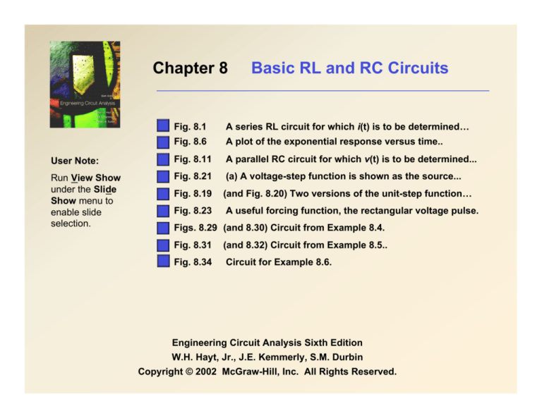
Chapter 8
Basic RL and RC Circuits
Fig. 8.1
A series RL circuit for which i(t) is to be determined…
Fig. 8.6
A plot of the exponential response versus time..
User Note:
Fig. 8.11
A parallel RC circuit for which v(t) is to be determined...
Run View Show
under the Slide
Show menu to
enable slide
selection.
Fig. 8.21
(a) A voltage-step function is shown as the source...
Fig. 8.19
(and Fig. 8.20) Two versions of the unit-step function…
Fig. 8.23
A useful forcing function, the rectangular voltage pulse.
Figs. 8.29 (and 8.30) Circuit from Example 8.4.
Fig. 8.31
(and 8.32) Circuit from Example 8.5..
Fig. 8.34
Circuit for Example 8.6.
Engineering Circuit Analysis Sixth Edition
W.H. Hayt, Jr., J.E. Kemmerly, S.M. Durbin
Copyright © 2002 McGraw-Hill, Inc. All Rights Reserved.
A series RL circuit for which i(t)
is to be determined, subject to
the initial condition that i(0) = I0.
( ( ))
d
KVL: R i t + L
i t =0
dt
1st-order, linear, constant-coefficient, ordinary, homogeneous
()
()
differential equation. The solution form is i t = Ae!t .
()
RAe!t + L! Ae!t = 0 " R + ! L = 0 " ! = # R / L " i t = Ae# Rt / L .
To find A we need a boundary condition. The most common boundary
()
condition is i 0 = I 0 . Then
()
I 0 = A " i t = I 0 e# Rt / L
W.H. Hayt, Jr., J.E. Kemmerly, S.M. Durbin, Engineering Circuit Analysis, Sixth Edition.
Copyright ©2002 McGraw-Hill. All rights reserved.
A plot of the exponential response versus time.
()
i t = I 0 e! Rt / L = I 0 e!t /" where " = L / R
W.H. Hayt, Jr., J.E. Kemmerly, S.M. Durbin, Engineering Circuit Analysis, Sixth Edition.
Copyright ©2002 McGraw-Hill. All rights reserved.
A parallel RC circuit for which
v(t) is to be determined,
subject to the initial condition
that v(0) = V0.
()
!t
v t
d
Ae
KCL: C
v t +
= 0 , v t = Ae!t " CA! e!t +
=0
dt
R
R
C ! + 1 / R = 0 " ! = #1 / RC " v t = Ae#t / RC
( ( ))
()
()
()
()
If v 0 = V0 , then v t = V0 e#t / RC = V0 e#t /$ , where $ = RC.
W.H. Hayt, Jr., J.E. Kemmerly, S.M. Durbin, Engineering Circuit Analysis, Sixth Edition.
Copyright ©2002 McGraw-Hill. All rights reserved.
(a) A voltage-step forcing function is shown as the source driving a
general network. (b) A simple circuit which, although not the exact
equivalent of part (a), may be used as its equivalent in many cases.
(c) An exact equivalent of part (a).
W.H. Hayt, Jr., J.E. Kemmerly, S.M. Durbin, Engineering Circuit Analysis, Sixth Edition.
Copyright ©2002 McGraw-Hill. All rights reserved.
g
The unit-step forcing
function u(t – t0).
The unit-step forcing
function u(t).
W.H. Hayt, Jr., J.E. Kemmerly, S.M. Durbin, Engineering Circuit Analysis, Sixth Edition.
Copyright ©2002 McGraw-Hill. All rights reserved.
g
r
The rectangular pulse
function
$0
!
v(t % t0 ) = #V0
!0
"
t < t0
t0 < t < t1
t > t1
W.H. Hayt, Jr., J.E. Kemmerly, S.M. Durbin, Engineering Circuit Analysis, Sixth Edition.
Copyright ©2002 McGraw-Hill. All rights reserved.
Driven RL Circuit
( ( ))
d
Ri t + L
i t = Vs u t
dt
Solution form is i t = Ae!t /" + I f , t > 0 where I f = i # .
()
()
()
()
" = L / R , I f = Vs / R $ i t = Ae! Rt / L + Vs / R
( ) ( )
i 0+ = i 0! = 0 = A + Vs / R $ A = !Vs / R
() (
)(
i t = Vs / R 1! e! Rt / L
)
, t >0
( )
Driven RC Circuit
( ) + C d v (t ) = I u (t )
(
)
R
dt
Solution form is v ( t ) = Ae + V , t > 0 where V
" = RC , V = RI $ v ( t ) = Ae
+ RI
v t
s
!t / "
f
!t / RC
f
( ) ( )
s
s
v 0+ = v 0! = 0 = A + RI s $ A = ! RI s
()
(
v t = RI s 1! e!t / RC
)
, t >0
f
( )
=v # .
Circuit for which a
complete response i(t) is
desired.
The desired current
response as a function of
time.
W.H. Hayt, Jr., J.E. Kemmerly, S.M. Durbin, Engineering Circuit Analysis, Sixth Edition.
Copyright ©2002 McGraw-Hill. All rights reserved.
(c)
(d)
(a) Pulse waveform; (b) Circuit driven by waveform (a); (c) ! = t0/2; (d) ! = 2t0.
W.H. Hayt, Jr., J.E. Kemmerly, S.M. Durbin, Engineering Circuit Analysis, Sixth Edition.
Copyright ©2002 McGraw-Hill. All rights reserved.
Find the capacitor voltage vC(t) and the current i(t) in the 200-"
resistor of the circuit shown in (a).
(a) Original circuit; (b) circuit valid for t # 0; (c) circuit for t $ 0.
W.H. Hayt, Jr., J.E. Kemmerly, S.M. Durbin, Engineering Circuit Analysis, Sixth Edition.
Copyright ©2002 McGraw-Hill. All rights reserved.

